CP40 service manual.pdf - 第172页
6. Computer (CP-40) Version Date WA QA CA Note 00 Nov04 O O O 6. Loosen Two Bolts(for Securing FDD) to Disconnect FDD. Note) For Assembly, Perform Revers e Procedures of Disassembly. Con nect Connector with Red Wire of S…
6. Computer
(CP-40)
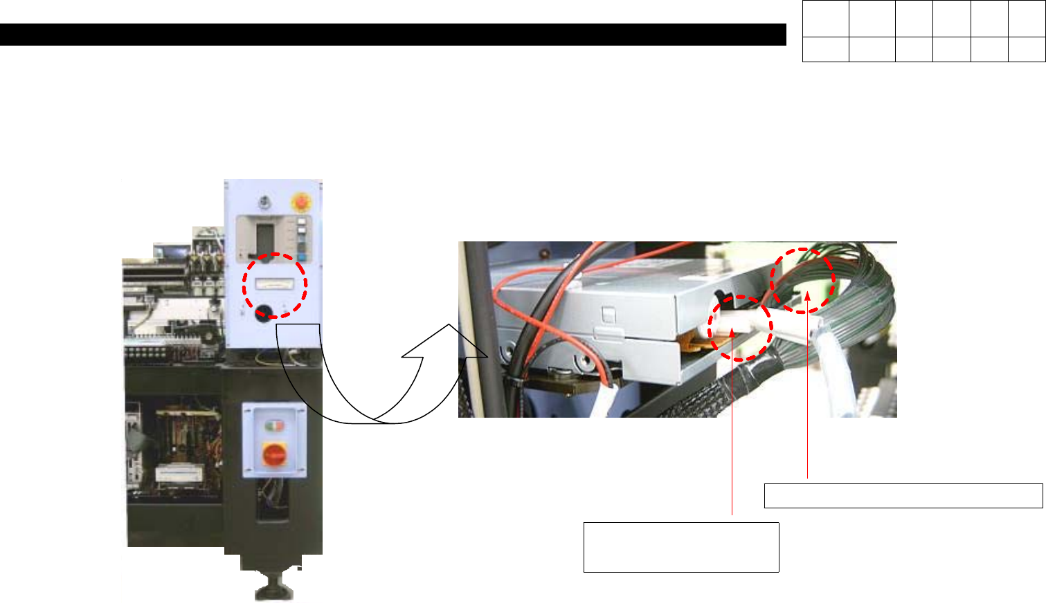
6. Disconnect Power Cable and Signal Cable in the Rear of FDD.
FDD Signal Cable Disconnection
FDD Power Cable
Disconnection
Version Date WA QA CA Note
00 Nov04 O O O
6. Computer
(CP-40)
Version Date WA QA CA Note
00 Nov04 O O O
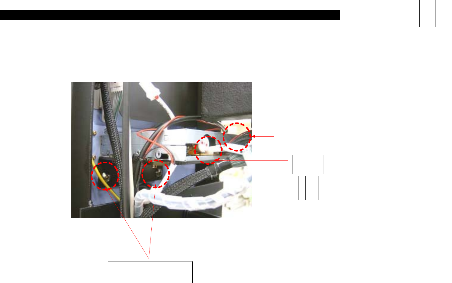
6. Loosen Two Bolts(for Securing FDD) to Disconnect FDD.
Note) For Assembly, Perform Reverse Procedures of Disassembly. Connect Connector with Red Wire of Signal
Cable toward the Inside.
Spherical Bolt(for
Securing FDD) 2ea
Note) Red Wire of Signal Cable
should be toward the Inside.
POWER
CABLE
+5V
+12V
12VG 5VG
6. Computer
(CP-40)
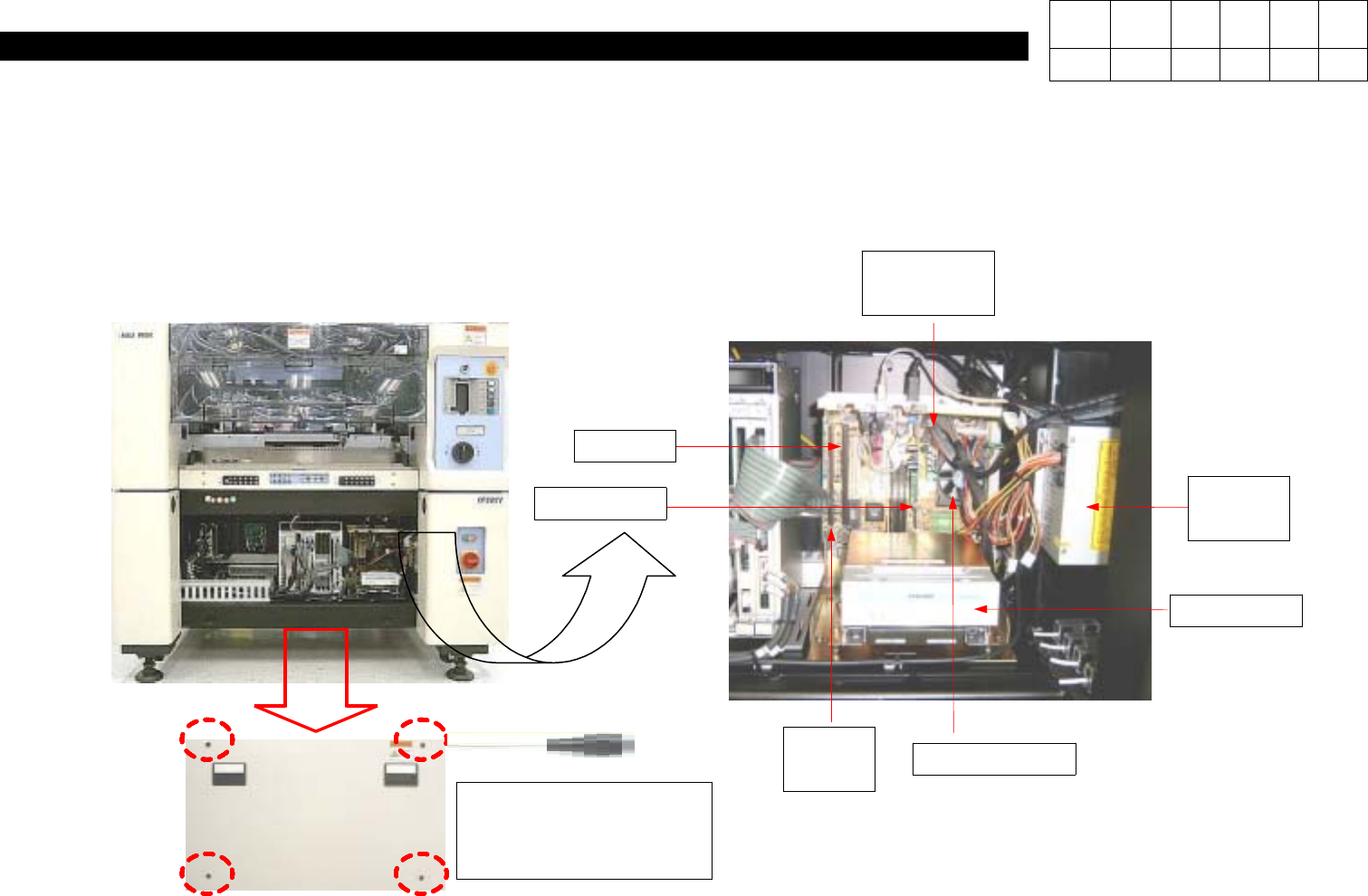
Spherical Bolt(for
Securing Front Cover)
4ea
1. Using Cross-head Screwdriver, Loosen Four Spherical Bolts to Open Front Cover.
2.
Determine the Area to be Repaired and Checked.
P/S only
for PC
CD ROM
CPU and FAN
RAM
VGA CARD
PC I/F
BOARD
MOTHER
BOARD
Version Date WA QA CA Note
00 Nov04 O O O
6-3-2.
Replacement of Old P/S with P/S only for PC