CP40 service manual.pdf - 第176页
6. Computer (CP-40) 6-3-3. Loose Contact of Board Check) Check Voltage Selector is Set to 115V . + 5 V 5 V G 1 2 V G + 1 2 V Check) Using Multi Tester, Check t he Voltage Supplied to Connector is Output Normally as Shown…
6. Computer
(CP-40)
5. Checkout
Material PC Power Supply, PC Power Bracket(J7052683A), Power Cable(Verify Machine Type.)
S/W
Tool Cross-head Screwdriver
6. Preparation
- Working Procedures
Equipment to be Replaced : CP-20, 40, 45, 55
1. Power OFF.
2. Remove Power Good Board and Cable(CN1).
3. Install PC Power Bracket and then PC Power Supply.
(Set Power Supply to 115V.)
4. Connect Properly Connector and Power Supply Cable Supplying Power to Mother Board.
Version Date WA QA CA Note
00 Nov04 O O O
6. Computer
(CP-40)
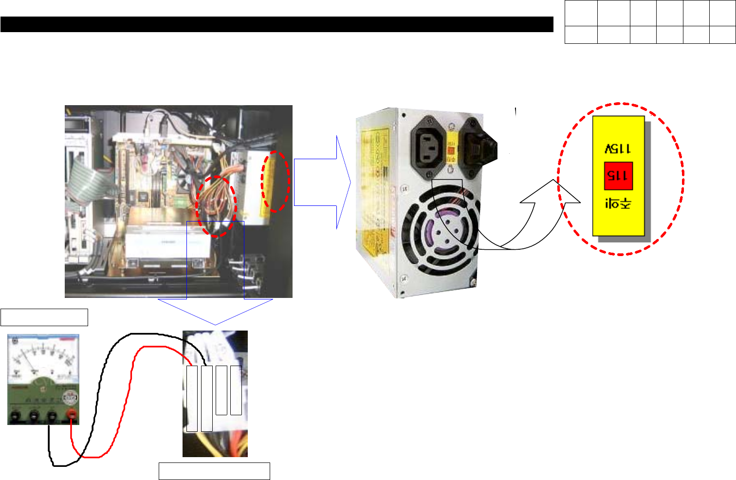
6-3-3.
Loose Contact of Board
Check)
Check Voltage Selector is Set to
115V
.
+
5
V
5
V
G
1
2
V
G
+
1
2
V
Check)
Using Multi Tester, Check the Voltage
Supplied to Connector is Output Normally
as Shown in the Left Figure.
V
Multi Tester
Power Connector
Version Date WA QA CA Note
00 Nov04 O O O
6. Computer
(CP-40)
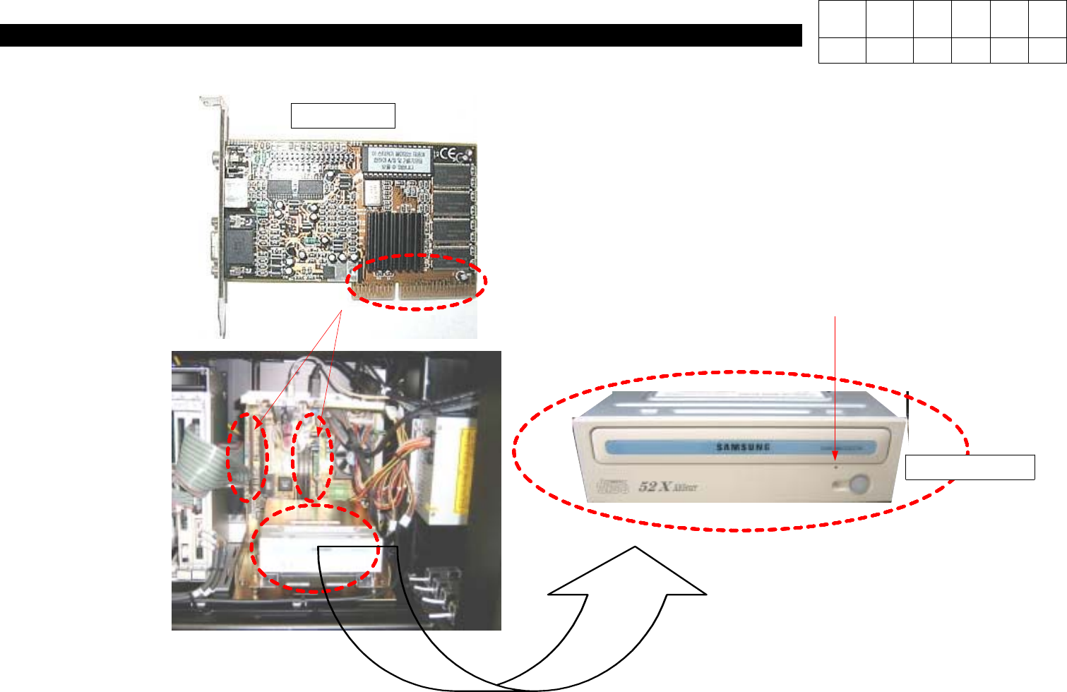
6-3-4.
Graphic Card Replacement
Check)
If Loose Contact of PC I/F Board or VGA
Card is Suspected, Disconnect Board and
Remove Foreign Material from Contact
SurfacewithErasertoReinsert.
Check)
With CD Inserted within CD-ROM,
Pressing Hole with Pin Makes CD
Come out of CD-ROM Manually.
Manual Hole
VGA CARD
Version Date WA QA CA Note
00 Nov04 O O O