CP40 service manual.pdf - 第27页
MODULE ERROR CODE Symptom and Cause ACTION Service Manual $8111 Aligner Zero Count Reset Error (Head 1) Pulse counter of aligner fails to be initialized to 0 after finding out Home position of θ -axis.(Communication Erro…
MODULE
ERROR
CODE
Symptom and Cause ACTION
Service
Manual
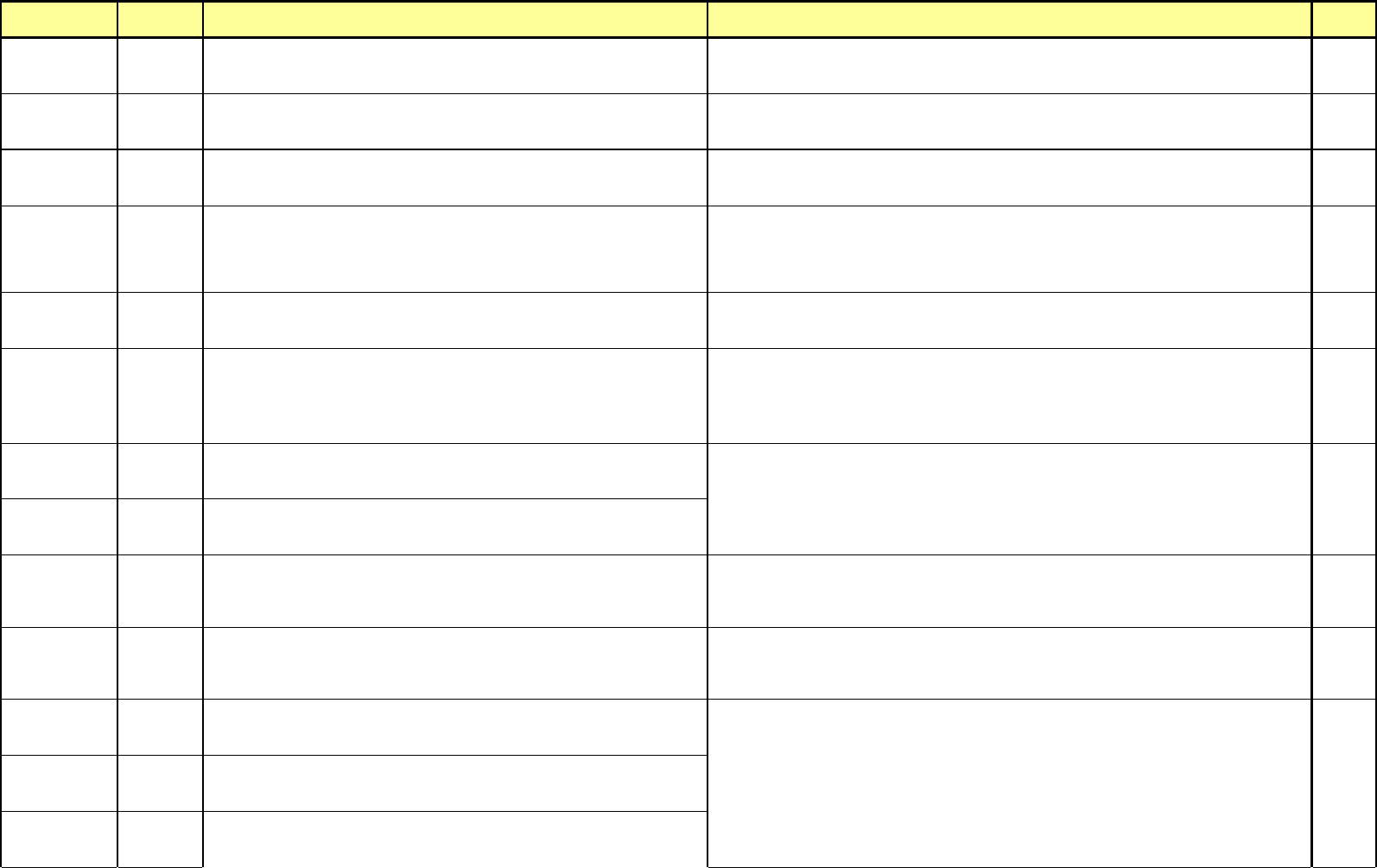
$5413
Sequence error in the tray feeder unit #2
Occurs when pallet No. sent to Component Placer after completing of pallet load is
different with Pallet No. requested from Component Placer.
$5414
Tray Data Transfer Error tray feeder unit #2
Occurs when Component Placer requests incorrect pallet No. to tray feeder.
(For Component Placer, this occurs when incorrect step No. is occurred.)
Check again after reloading the work PCB file.
12-3-8
12-3-9
Tray Feeder
Part
$5415
Tray ID error in the tray feeder unit #2
Occurs when trying to I/F with tray feeder undefined with software.
Check again after reloading the work PCB file.
12-3-8
12-3-9
$5416
Moving Timeout error in the tray feeder unit #2
Occurs when only message of "Tray feeder is moving continuously" is given when
Component Placer requests specific pallet.
After Stop/Reset or Emergency Stop, operate the system again.
Operate the system again after turning power of Tray Feeder On/Off.
Check Tray Feeder and link cable for proper connections.
Check for conditions of I/F board in Tray Feeder.
$5417
Tray step search error in the tray feeder unit #2
Occurs when tray fails to be defined in step when checking the step for requesting
Pallet of Tray.
Check again after reloading the work PCB file.
12-3-8
12-3-9
$5418
Not ready error in the tray feeder unit #2
Occurs when no response is taken from tray feeder in requesting pallet to Tray
Feeder.
After Stop/Reset or Emergency Stop, operate the system again.
Operate the system again after turning power of Tray Feeder On/Off.
Check Tray Feeder and link cable for proper connections.
Check for conditions of I/F board in Tray Feeder.
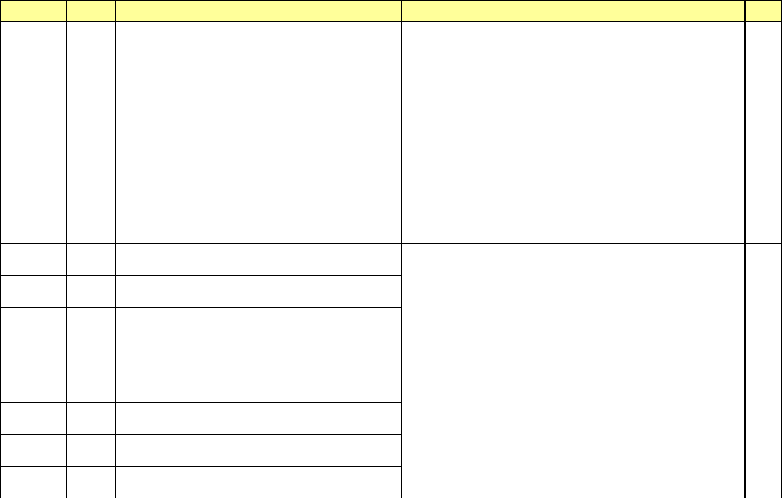
$5601
Tray Feeder #1 Manual command call error
Occurs when Component Placer fails to send command to tray feeder #1 with test
mode.
$5602
Tray Feeder #2 Manual command call error
Occurs when Component Placer fails to send command to tray feeder #2 with test
mode.
$6000
Homing error in AUTO mode
Error occurred in course of homing when restart just after PCB file loading or
reseting.
Try to do homing again with teaching box at IDLE.
If failed to homing, check for mechanical conditions of axis concerned, cable connected conditions or
driver conditions.
9-3-1
9-3-2
9-3-3
$6002
Z Axis Move Error
Occurs when position error of final moving after Z axis moving exceeds Z axis
resolution.
Operate a system again after Stop/Reset.
Operate a system after Emergency stop.
Check for mechanical contact conditions of Head Z axis.
Woori Align
Part
$8101
Aligner initialize Error (Head 1)
Fails to initialize Aligner. (Communication Error).
$8102
Aligner initialize Error (Head 2)
Fails to initialize Aligner. (Communication Error).
1-3-1
7-3-1
$8103
Aligner initialize Error (Head 3)
Fails to initialize Aligner.(Communication Error).
Try again after stop/reset or Emergency Stop of Component Placer and tray feeder.
Check conditions of Tray Feeder and cable links.
Try again after turning power of Tray Feeder On/Off.
Check for LED of I/F board in Tray Feeder.
Try again after finding out again Home position by turning on the Aligner DSP Board by pressing and
releasing the <Emergency> switch of operation panel or teaching box.
Check for cable linked conditions between Aligner DSP Board and VME RS-232C I/F Board.
- 13 -
MODULE
ERROR
CODE
Symptom and Cause ACTION
Service
Manual
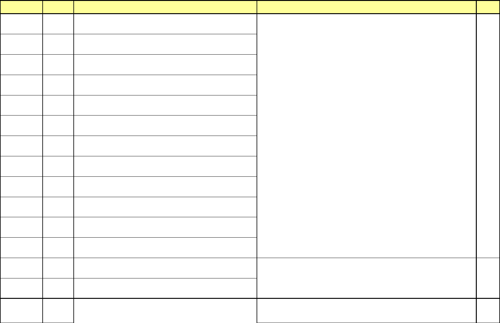
$8111
Aligner Zero Count Reset Error (Head 1)
Pulse counter of aligner fails to be initialized to 0 after finding out Home position of θ
-axis.(Communication Error).
$8112
Aligner Zero Count Reset Error (Head 2)
Pulse counter of aligner fails to be initialized to 0 after finding out Home position of θ
-axis.(Communication Error).
1-3-1
7-3-1
$8113
Aligner Zero Count Reset Error (Head 3)
Pulse counter of aligner fails to be initialized to 0 after finding out Home position of θ
-axis.(Communication Error).
$8141
Data Load Error (Head 1)
Fails to transfer Theta offset command to Aligner DSP board.(Communication
error).
$8142
Data Load Error (Head 2)
Fails to transfer Theta offset command to Aligner DSP board.(Communication
error).
1-3-1
7-3-1
$8143
Data Load Error (Head 3)
Fails to transfer Theta offset command to Aligner DSP board.(Communication
error).
$8211
Data Load Error (Head 1)
Fails to transfer part to align to aligner DSP board.(Communication error).
Woori Align
Part
$8212
Data Load Error (Head 2)
Fails to transfer information on part to align to aligner DSP board.(Communication
error).
$8213
Data Load Error (Head 3)
Fails to transfer information on part to align to aligner DSP board.(Communication
error).
$8241
Align Start Error (Head 1)
Communication error occurs when executing Align.
$8242
Align Start Error (Head 2)
Communication error occurs when executing Align.
$8243
Align Start Error (Head 3)
Communication error occurs when executing Align.
$8251
Align result response error (Head 1)
Fails to receive the results of align caused by communication error.
1-3-2
$8252
Align result response error (Head 2)
Fails to receive the results of align caused by communication error.
1-3-3
$8253
Align result response error (Head 3)
Fails to receive the results of align caused by communication error.
1-3-6
Try again after finding out again Home position by turning on the Aligner DSP Board by pressing and
releasing the <Emergency> switch of operation panel or teaching box.
Check for cable linked conditions between Aligner DSP Board and VME RS-232C I/F Board.
Try again after finding out again Home position by turning on the Aligner DSP Board by pressing and
releasing the <Emergency> switch of operation panel or teaching box.
Check for cable linked conditions between Aligner DSP Board and VME RS-232C I/F Board.
- 14 -
MODULE
ERROR
CODE
Symptom and Cause ACTION
Service
Manual
$8271
Object size caliper error (Head 1)
Fails to receive the object size measurement command caused by communication
error.
7-3-1
$8272
Object size caliper error (Head 2)
Fails to receive the object size measurement command caused by communication
error.
$8273
Object size caliper error (Head 3)
Fails to receive the object size measurement command caused by communication
error.
$8311
Nozzle find Error (Head 1)
Communication error occurs when Z-axis finds out Align height of Nozzle.
$8312
Nozzle find Error (Head 2)
Communication error occurs when Z-axis finds out Align height of Nozzle.
$8313
Nozzle find Error (Head 3)
Communication error occurs when Z-axis finds out Align height of Nozzle.
$8321
Nozzle Inspection Error (Head 1)
Communication error occurs when θ-axis inspects run-out of nozzle.
$8322
Nozzle Inspection Error (Head 2)
Communication error occurs when θ-axis inspects run-out of nozzle.
$8323
Nozzle Inspection Error (Head 3)
Communication error occurs when θ-axis inspects run-out of nozzle.
$8331
Nozzle Inspection Result Error (Head 1)
Communication error occurs when θ-axis inspects run-out of nozzle.
$8332
Nozzle Inspection Result Error (Head 2)
Communication error occurs when θ-axis inspects run-out of nozzle.
$8333
Nozzle Inspection Result Error (Head 3)
Communication error occurs when θ-axis inspects run-out of nozzle.
$8341
Nozzle Check Error. Please check Nozzle. (Head 1)
Occurs when nozzle exists actually in head however program indicates no nozzle
exists in the head.
4-3-2
$8342
Nozzle Check Error. Please check Nozzle. (Head 2)
Occurs when nozzle exists actually in head however program indicates no nozzle
exists in the head.
4-3-4
Woori Align
Part
$8343
Nozzle Check Error. Please check Nozzle. (Head 3)
Occurs when nozzle exists actually in head however program indicates no nozzle
exists in the head.
Check for abnormal conditions of Nozzle data in dialog box displayed after executing the command
of <Setup/ANC Setting> in MMI.
4-3-2
4-3-4
Try again after finding out again Home position by turning on the Aligner DSP Board by pressing and
releasing the <Emergency> switch of operation panel or teaching box.
Check for cable linked conditions between Aligner DSP Board and VME RS-232C I/F Board.
Check for abnormal conditions of Nozzle data in dialog box displayed after executing the command
of <Setup/ANC Setting> in MMI.
- 15 -