CP40 service manual.pdf - 第169页
6. Computer (CP-40) 6-3-1. FDD Replacement 1. Disconnect Key Board, Mouse and Teaching Box from E quipment. 2. Raise Acrylic Cover and Loosen Three M3*6 Flush Bolts to Disconnect Stay. Stay M3*6 3ea 2 3 3. Using T-Wrench…
6. Computer
(CP-40)
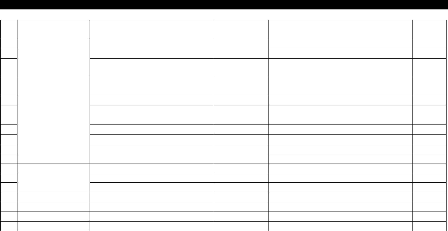
NO Symptom Possible Cause Error Code Action
Instructio
n
1
Disk Driver Malfunction
File cannot be Read from FDD.
Check FDD Signal Cable Direction.
6-3-1
2
Replace FDD.
6-3-1
3
OS does not Operate after CMOS
Booting.
Replace HDD.
4
Board Malfunction
Equipment does not Operate after OS
Booting.
Clean and Replace PC I/F Contact. 6-3-3
5 CMOS Battery Error Replace Mother Board. 6-3-3
6
Booting is not Achieved after Power
ON.
Reset VGA Card and Replace Mother Board. 6-3-3
7 Back Up Battery Error Replace Battery and Mother Boar 6-3-2
8 PC Down Reboot Windows and Replace Mother Board.
9
Screen is display on Monitor.
Reinstall VGA Card Driver. 6-3-4
10 Replace VGA CARD 6-3-4
11
Peripheral Device
Monitor Screen is Changed. Replace Monitor.
12 Mouse Point is Changed Quickly. Reinstall and Replace Driver.
13 Bad Key Board Replace Key Board.
14
15
16
17
6-2. Trouble Diagnosis
6. Computer
(CP-40)
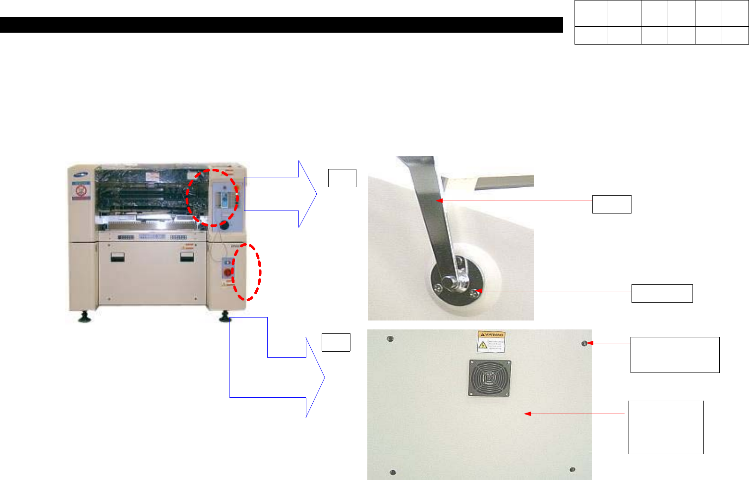
6-3-1. FDD Replacement
1. Disconnect Key Board, Mouse and Teaching Box from Equipment.
2. Raise Acrylic Cover and Loosen Three M3*6 Flush Bolts to Disconnect Stay.
Stay
M3*6 3ea
2
3
3. Using T-Wrench, Loosen Four
Wrench Bolts to Disconnect
Lower Right-hand Cover.
Wrench Bolt
4ea
Lower
Right-hand
Cover
Version Date WA QA CA Note
00 Nov04 O O O
6. Computer
(CP-40)
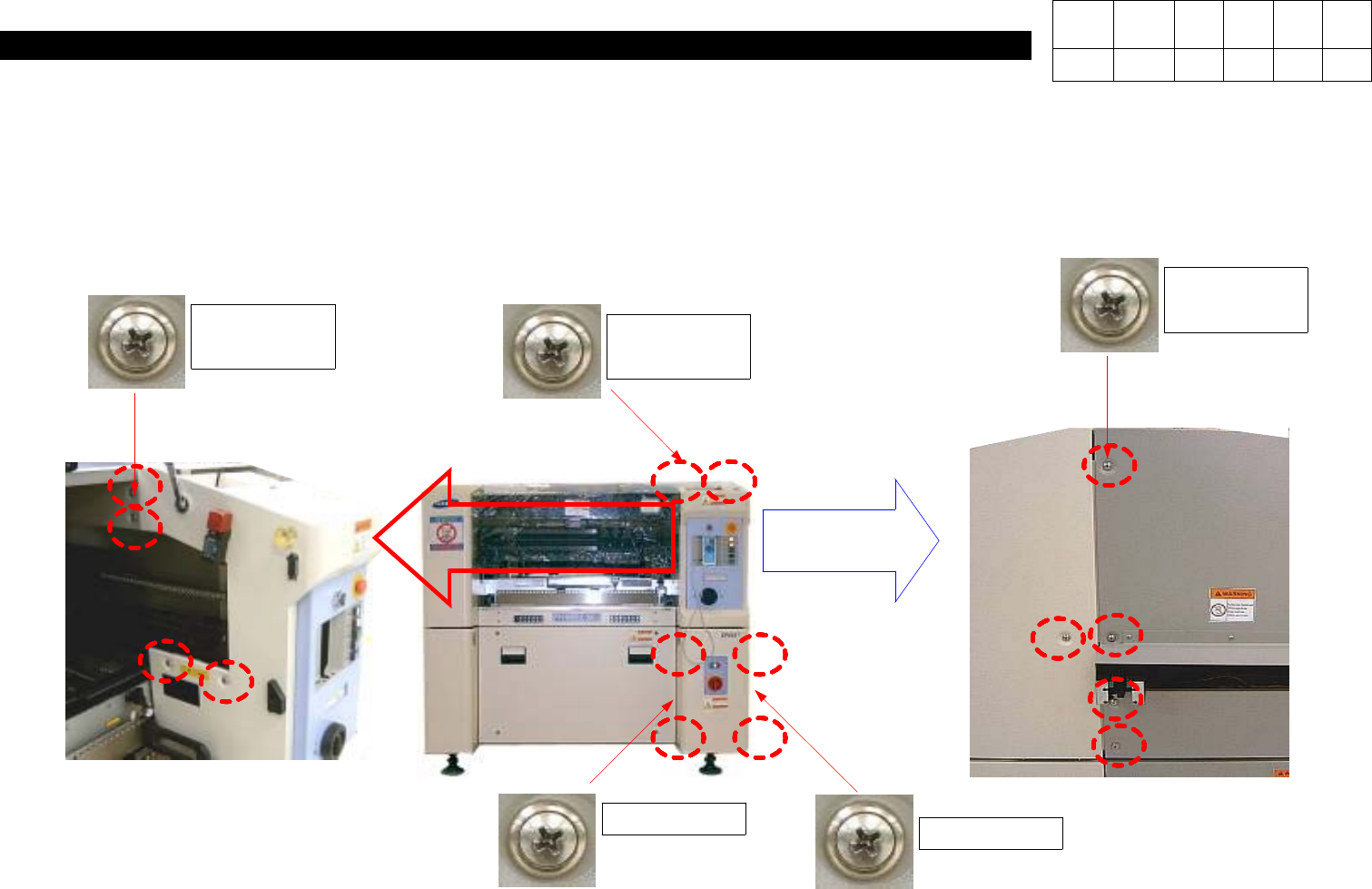
4. Lower Front Cover Disconnection => Loosen Four Toras Bolts to Disconnect Lower Front Cover.
5. Upper Front Cover Disconnection =>
5-1. Loosen Five(Right), Two(Upper) and Four(Left) Toras Bolts.
5-2. Loosen Four Black Wrench Bolts under Upper Cover.
Left
Toras 4ea
Upper
Toras 2ea
Right
Toras 5ea
Toras 2ea
Toras 2ea
Version Date WA QA CA Note
00 Nov04 O O O