CP40 service manual.pdf - 第65页
0. Install & Driver (CP-40) Version Date WA QA CA Note 00 Nov04 O O O Locate the head to the center P l a c ei tt ot h e location that 9 LM Rail volts are shown . P l a c ei tt ot h el o c a t i o n that 11 LM Rail v…
0. Install & Driver
(CP-40)
Version Date WA QA CA Note
00 Nov04 O O O
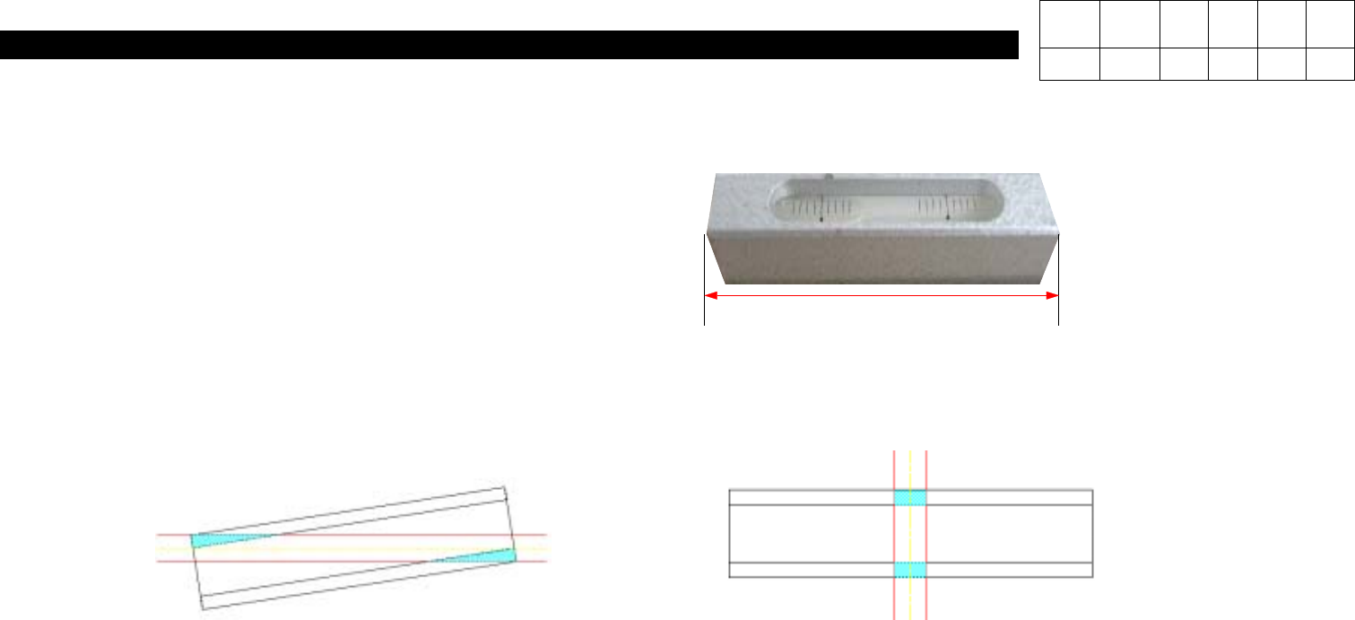
< Level Setting >
1. LEVELER
: Use 100mm width measuring machine that is
possible to acquire 0.02(mm/m) of precision.
2. Installation method of leveler (Differ by contacting part)
: The leveling should be performed at the level of being on the surface but less than 30% of bottom is being
contacted to the ground when installed on the LM-RAIL
-> The condition of leveling is differed by the installation location of leveler.
Contacting rate : 28% Contacting rate : 12%
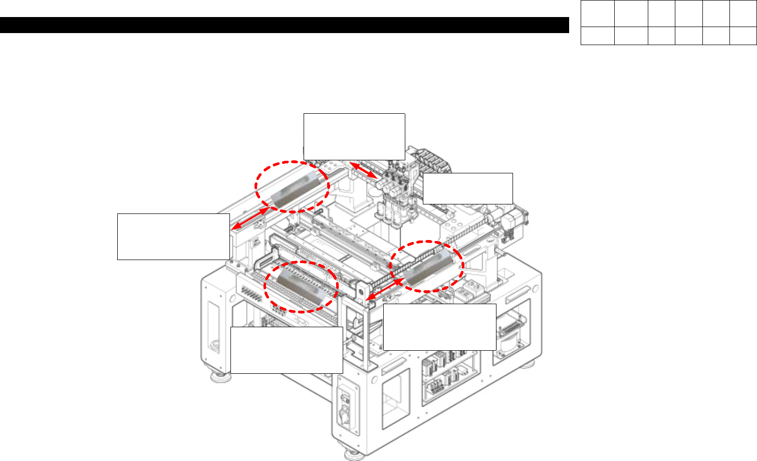
3. Installation location of leveler
: The leveling condition is differed by the installation location of leveler and location head and X-frame.
-. Back & Forth: Install it vertically (back & forth) to center of Y1 and Y2 rails.
-. Right & Left: Install to the center of Feeder Base on the front.
Special attention is required to prevent interference by locating the Hole cap of center on center groove of the leveler.
100mm
0. Install & Driver
(CP-40)
Version Date WA QA CA Note
00 Nov04 O O O
Locate the head
to the center
Placeittothe
location that 9 LM
Rail volts are shown.
Placeittothelocation
that 11 LM Rail volts
are shown.
Placeittothelocation
that 11 LM Rail volts
are shown.
Place the center of the
hole cap on the groove
of the leveler
0. Install & Driver
(CP-40)
Version Date WA QA CA Note
00 Nov04 O O O
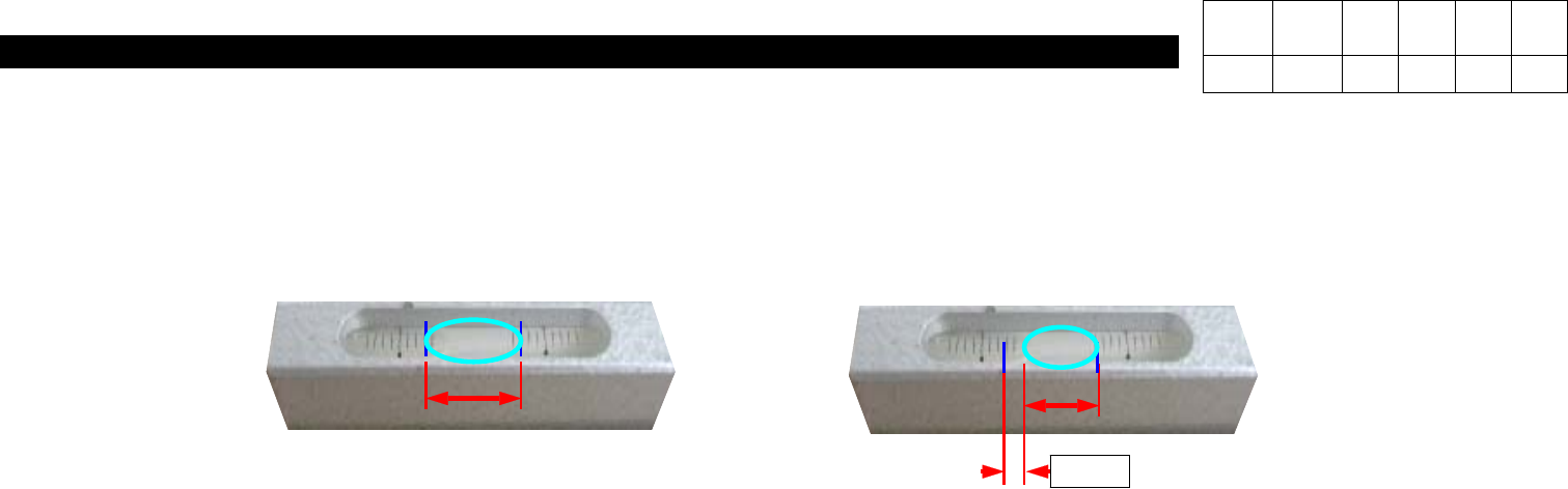
2.0
-. Standard 0.05mm/m
: within 2.5 of leveler scale
=> Set within 2.0 (Leveler error, Measurement error)
-. Leveling is required after the movement of equipment
(To prevent the transformation by leaving without leveling)
- The party who move the equipment has to perform the leveling.