CP40 service manual.pdf - 第148页
4. Feeder Base & ANC (CP-40) INPUT SENSOR PLACE STOPPER HOLE FIXER OUTPUT SENSOR PLACE SENSOR WAIT SENSOR 17 18 19 20 21 22 23 24 25 26 27 28 29 30 31 32 J9800393 Conveyor I/F Board Ass'y 19 Up 20 Down J3212025A…
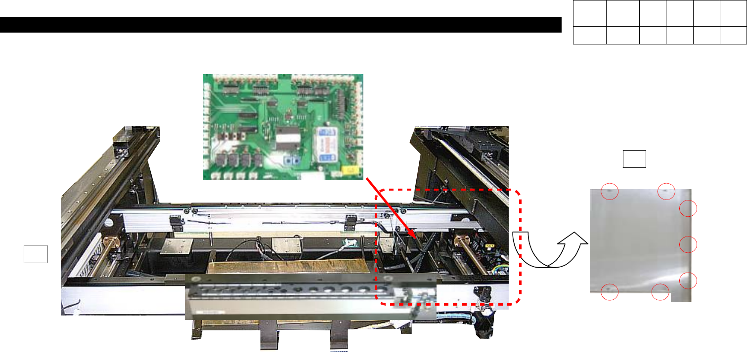
4. Feeder Base & ANC
(CP-40)
1) Using Teaching Box, Move Head to the Rear.
2) Turning Conveyor Width Adjusting Handle to Left-hand to Widen the Conveyor Width as
Wide as Possible.
3) Loosen Seven M3*6 Toras Bolts to Open Chip Cover on the Left-hand inside Equipment.
4) Disconnect Connector on PCB.
5) Loosen Six Spherical Head Bolts to Disconnect Feeder I/F Board.
6) Replace New PCB and Assemble it according to Reverse Procedures.
J9800393
Conveyor I/F Board Ass'y
J2102038
Chip Cover Side 2
3
2
Version Date WA QA CA Note
00 Nov04 O O O
4-3-7. Conveyor I/F Board Replacement
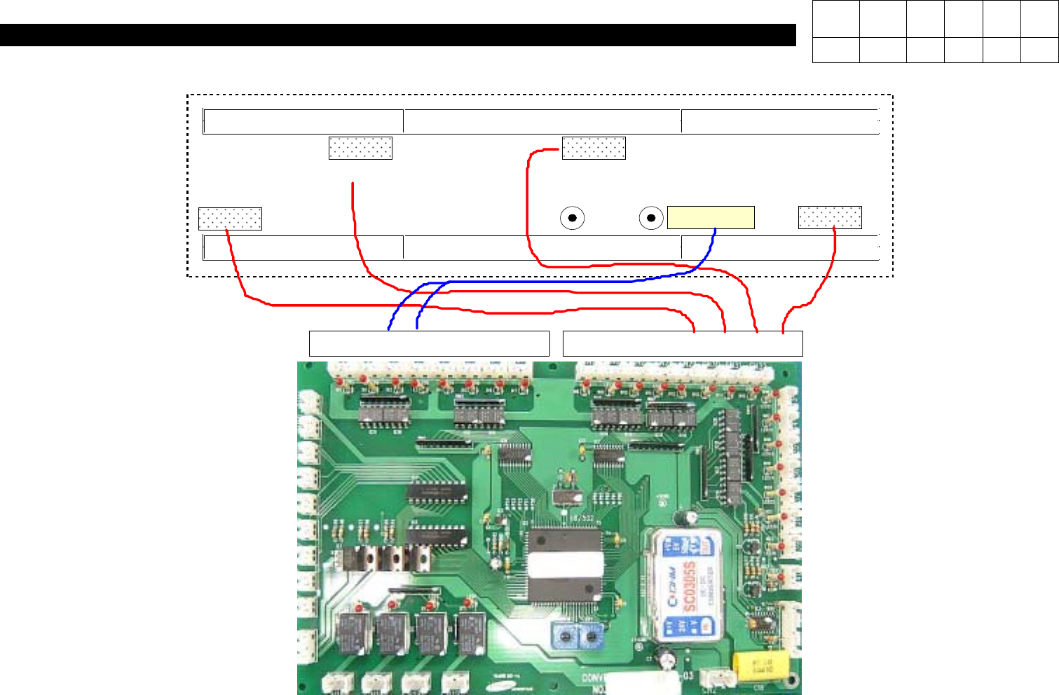
4. Feeder Base & ANC
(CP-40)
INPUT SENSOR
PLACE STOPPER
HOLE
FIXER
OUTPUT SENSOR
PLACE SENSOR
WAIT SENSOR
17 18 19 20 21 22 23 24 25 26 27 28 29 30 31 32
J9800393
Conveyor I/F Board Ass'y
19 Up
20 Down
J3212025A
SENSOR (Former J1301569)
CN29 CV17-1
CN30 CV18-1
CN31 CV19-1
CN32 CV20-1
Version Date WA QA CA Note
00 Nov04 O O O
4-3-8. Conveyor I/F Board Cable Check
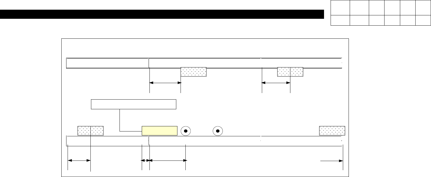
4. Feeder Base & ANC
(CP-40)
<Single-stage Conveyor> <2-stage Conveyor> <3-stage Conveyor>
OUT SENSOR PLACE STOPPER
HOLE
FIXER
INPUT SENSOR
#Based on White Block
PLACE SENSOR WAIT SENSOR
100mm 45mm
45mm 15mm 950mm 0mm
<Fig. 1> CP-40L(V) Conveyor Right => Left Assembly View
<Working Procedures>
1)As Shown in Above Figure, Secure Sensors on Each Position Properly.
2)Secure White Block(for Securing Place Stopper) Between Single-stage and 2-stage Conveyors according
to Each Dimension.
3)Secure Place Stopper on Left Block.
4)Exchange the Left and the Right of AC Motor.
5)Set PCB Origin to Front Left and the Direction of 2-stage Conveyor to CCW.
-.Refer to Fig. 2.
Version Date WA QA CA Note
00 Nov04 O O O
4-3-9. Conveyor Right => Left Change