CP40 service manual.pdf - 第31页
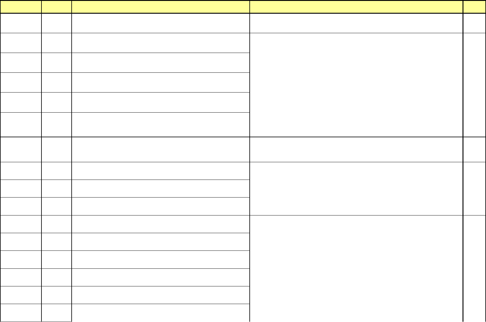
MODULE ERROR CODE Symptom and Cause ACTION Service Manual $8871 Aligner out of heap memory[07] (Head 1) Error occurs to memory of Aligner DSP Board. $8872 Aligner out of heap memory[07] (Head 2) Error occurs to memory of…
MODULE
ERROR
CODE
Symptom and Cause ACTION
Service
Manual
$8743
Please check nozzle in the Head (Head 3)
Nozzle fails to be inserted securely into Head securely.
$8821
Aligner Received Unknown Command From Host[02] (Head 1)
Aligner DSP Board is received unknown command from Host(Component Placer).
$8822
Aligner Received Unknown Command From Host[02] (Head 2)
Aligner DSP Board is received unknown command from Host(Component Placer)
1-3-1
$8823
Aligner Received Unknown Command From Host[02] (Head 3)
Aligner DSP Board is received unknown command from Host(Component Placer).
7-3-1
$8831
Aligner Sent Unknown Command From Host[03] (Head 1)
Host(Component Placer) sent unknown command to Aligner DSP Board.
$8832
Aligner Sent Unknown Command From Host[03] (Head 2)
Occurs when Host(Component Placer) transfers unknown command to Aligner DSP
Board.
Woori Align
Part
$8833
Aligner Sent Unknown Command From Host[03] (Head 3)
Occurs when Host(Component Placer) transfers unknown command to Aligner DSP
Board.
Try again after finding out again Home position by turning on the Aligner DSP Board by pressing and
releasing the <Emergency> switch of operation panel or teaching box.
Check for cable linked conditions between Aligner DSP Board and VME RS-232C I/F Board.
1-3-1
7-3-1
$8841
Aligner received zero length message[04] (Head 1)
Occurs when Aligner DSP Board receives incorrect data from Host(Component
Placer).
1-3-1
$8842
Aligner received zero length message[04] (Head 2)
Occurs when Aligner DSP Board receives incorrect data from Host(Component
Placer).
7-3-1
$8843
Aligner received zero length message[04] (Head 3)
Occurs when Aligner DSP Board receives incorrect data from Host(Component
Placer).
$8851
Aligner failed to write to Host[05] (Head 1)
Occurs when Aligner DSP Board can not respond to Host(Component Placer).
$8852
Aligner failed to write to Host[05] (Head 2)
Occurs when Aligner DSP Board can not respond to Host(Component Placer).
$8853
Aligner failed to write to Host[05] (Head 3)
Occurs when Aligner DSP Board can not respond to Host(Component Placer).
1-3-1
$8861
Aligner failed to read from Host[06] (Head 1)
Occurs when Aligner DSP Board can not receive data from Host(Component
Placer).
1-3-3
$8862
Aligner failed to read from Host[06] (Head 2)
Occurs when Aligner DSP Board can not receive data from Host(Component
Placer).
$8863
Aligner failed to read from Host[06] (Head 3)
Occurs when Aligner DSP Board can not receive data from Host(Component
Placer).
Try again after finding out again Home position by turning on the Aligner DSP Board by pressing and
releasing the <Emergency> switch of operation panel or teaching box.
Check for cable linked conditions between Aligner DSP Board and VME RS-232C I/F Board.
Try again after finding out again Home position by turning on the Aligner DSP Board by pressing and
releasing the <Emergency> switch of operation panel or teaching box.
Check for cable linked conditions between Aligner DSP Board and VME RS-232C I/F Board.
- 17 -
MODULE
ERROR
CODE
Symptom and Cause ACTION
Service
Manual
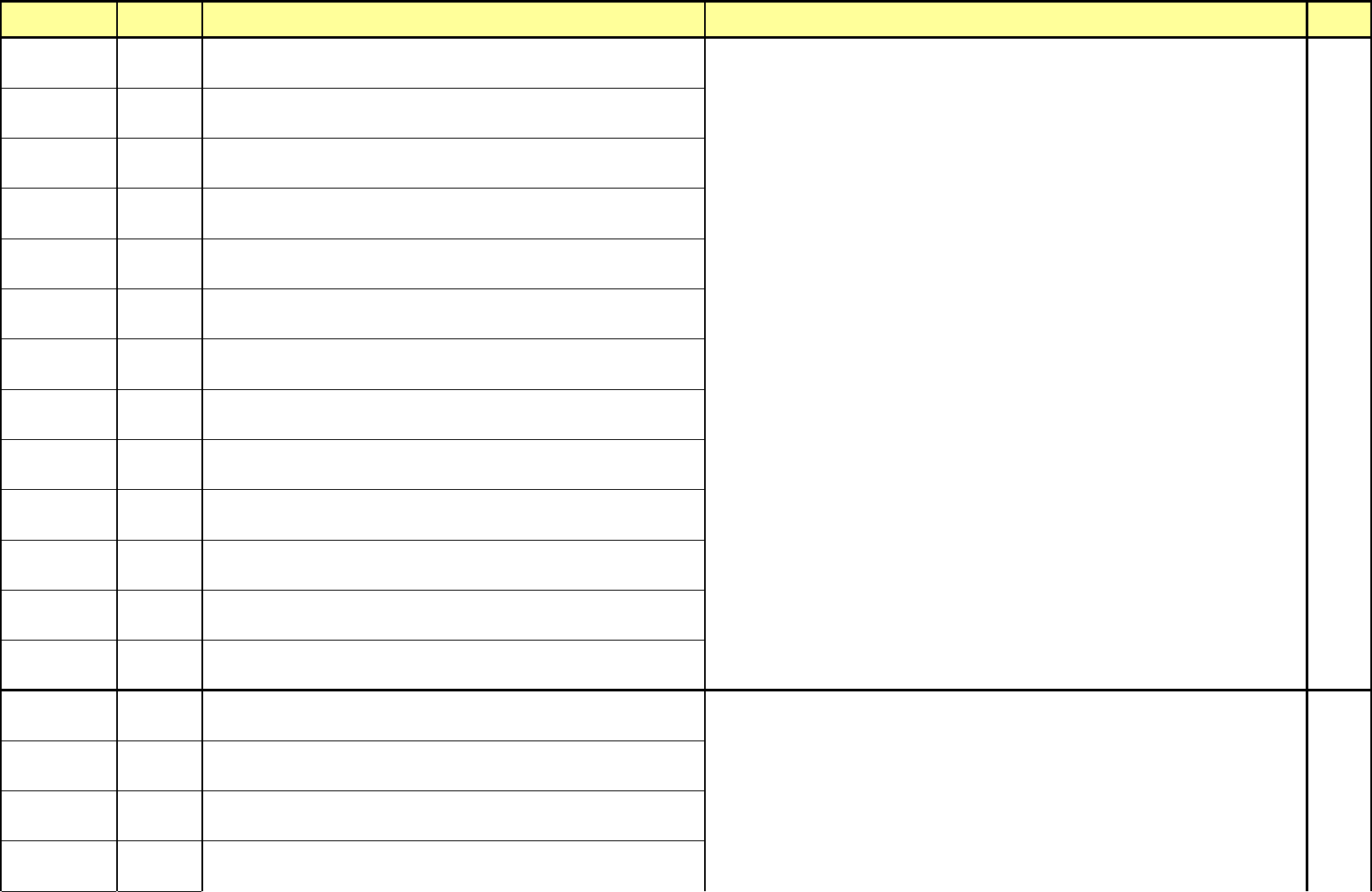
$8871
Aligner out of heap memory[07] (Head 1)
Error occurs to memory of Aligner DSP Board.
$8872
Aligner out of heap memory[07] (Head 2)
Error occurs to memory of Aligner DSP Board.
$8873
Aligner out of heap memory[07] (Head 3)
Error occurs to memory of Aligner DSP Board.
$8881
Aligner received invalid length of message[08] (Head 1)
Aligner DSP Board receives invalid data from Host(Component Placer).
$8882
Aligner received invalid length of message[08] (Head 2)
Aligner DSP Board receives invalid data from Host(Component Placer).
$8883
Aligner received invalid length of message[08] (Head 3)
Aligner DSP Board receives invalid data from Host(Component Placer).
$8891
Aligner Received Bad Reply Length[09] (Head 1)
Aligner DSP Board receives invalid data from Host(Component Placer).
$8892
Aligner Received Bad Reply Length[09] (Head 2)
Aligner DSP Board receives invalid data from Host(Component Placer).
$8893
Aligner Received Bad Reply Length[09] (Head 3)
Aligner DSP Board receives invalid data from Host(Component Placer).
$88A1
Aligner RAM Failed[10] (Head 1)
Error occurred to memory of Aligner DSP Board.
$88A2
Aligner RAM Failed[10] (Head 2)
Error occurred to memory of Aligner DSP Board.
$88A3
Aligner RAM Failed[10] (Head 3)
Error occurred to memory of Aligner DSP Board.
$88C1
Aligner Position Counter circuitry failed[12] (Head 1)
Error occurred to position counter circuit of Aligner DSP Board.
Woori Align
Part
$88C2
Aligner Position Counter circuitry failed[12] (Head 2)
Error occurred to position counter circuit of Aligner DSP Board.
$88C3
Aligner Position Counter circuitry failed[12] (Head 3)
Error occurred to position counter circuit of Aligner DSP Board.
$88D1
Aligner unable to reset the theta position counter[13] (Head 1)
Error occurred to position counter circuit of Aligner DSP Board.
$88D2
Aligner unable to reset the theta position counter[13] (Head 2)
Error occurred to position counter circuit of Aligner DSP Board.
1-3-1
Try again after finding out again Home position by turning on the Aligner DSP Board by pressing and
releasing the <Emergency> switch of operation panel or teaching box.
Check for cable linked conditions between Aligner DSP Board and VME RS-232C I/F Board.
- 18 -
MODULE
ERROR
CODE
Symptom and Cause ACTION
Service
Manual
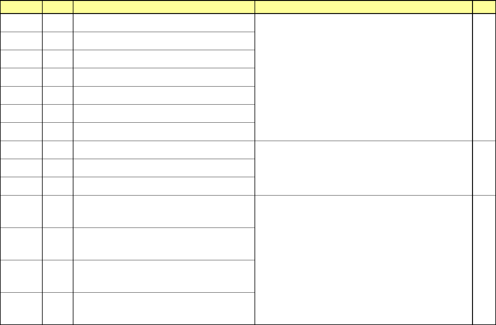
$88D3
Aligner unable to reset the theta position counter[13] (Head 3)
Error occurred to position counter circuit of Aligner DSP Board.
7-3-1
$88E1
Aligner image acquisition circuitry failed[14] (Head 1)
Error occurred to Aligner DSP Board.
$88E2
Aligner image acquisition circuitry failed[14] (Head 2)
Error occurred to Aligner DSP Board.
$88E3
Aligner image acquisition circuitry failed[14] (Head 3)
Error occurred to Aligner DSP Board.
$88F1
Aligner AD converter circuitry failed[15] (Head 1)
Error occurred to Aligner DSP Board.
$88F2
Aligner AD converter circuitry failed[15] (Head 2)
Error occurred to Aligner DSP Board.
$88F3
Aligner AD converter circuitry failed[15] (Head 3)
Error occurred to Aligner DSP Board.
$8921
Aligner failed nozzle find[18] (Head 1)
Aligner failed to set the align position of nozzle.
1-3-1
$8922
Aligner failed nozzle find[18] (Head 2)
Aligner failed to set the align position of nozzle.
7-3-1
$8923
Aligner failed nozzle find[18] (Head 3)
Aligner fails to set the align position of nozzle.
$89B1
Aligner inspected bad x dimension[27] (Head 1)
X size of part measured by Aligner exceeds the tolerance of size X registered. This
occurs caused by pickup(tombstome) with part upwards, failure of part pickup,
incorrectly inputted scan size of part, or incorrect align height of part.
$89B2
Aligner inspected bad x dimension[27] (Head 2)
X size of part measured by Aligner exceeds the tolerance of size X registered. This
occurs caused by pickup(tombstome) with part upwards, failure of part pickup,
incorrectly inputted scan size of part, or incorrect align height of part.
12-3-3
$89B3
Aligner inspected bad x dimension[27] (Head 3)
X size of part measured by Aligner exceeds the tolerance of size X registered. This
occurs caused by pickup(tombstome) with part upwards, failure of part pickup,
incorrectly inputted scan size of part, or incorrect align height of part.
12-3-7
$89C1
Aligner inspected bad y dimension[28] (Head 1)
Y size of part measured by Aligner exceeds the tolerance of size Y registered. This
occurs caused by pickup(tombstome) with part upwards, failure of part pickup,
incorrectly inputted scan size of part, or incorrect align height of part.
12-3-8
Try again after releasing the error by pressing <Reset> switch of operation panel.
Check for cable linked conditions between Aligner DSP Board and VME RS-232C I/F Board.
Check that scan size of part registered is identical to that of real part.
Check that Align height of part is proper.
Check that thickness of part registered is identical to that of real part.
Check that tolerance of part is suitable.
Check that picked up condition of part and value of Z-axis inputted are suitable.
Check for feeding condition of Feeder.
Try again after finding out again Home position by turning on the Aligner DSP Board by pressing and
releasing the <Emergency> switch of operation panel or teaching box.
Check for cable linked conditions between Aligner DSP Board and VME RS-232C I/F Board.
- 19 -