bnp-b2365(eng)b.pdf - 第123页
3. Setup 3 - 36 High-gain speci fications No. Abbrev. Parameter name Explanation F E D C B A 9 8 7 6 5 4 3 2 1 0 pabs rabs bit Meaning when "0" is set Meaning when "1" is set 0 1 rabs Normal setting R…

3. Setup
3 - 35
High-gain specifications
No. Abbrev. Parameter name Explanation
Setting range
(Unit)
SV060 TLMT
Collision detection
level
When using the collision detection function, set the collision detection level
during the G0 feeding.
If "0" is set, none of the collision detection function will work.
0 to 999
(Stall [rated]
current %)
SV061 DA1NO
D/A output channel
1 data No.
Input the data number you wish to output to D/A output channel.
In the case of MDS-C1-V2, set the axis on the side to which the data will
not be output to "-1".
SV062 DA2NO
D/A output channel
2 data No.
-1 to 127
SV063 DA1MPY
D/A output channel
1 output scale
Set the scale with a 1/256 unit.
When "0" is set, output is done with the standard output unit.
SV064 DA2MPY
D/A output channel
2 output scale
-32768 to
32767
(Unit: 1/256)
Set the spring constant of the tool end compensation.
In the semi-closed loop control, the tool end compensation amount is
calculated with the following equation.
F (mm/min)
2
× SV065
Compensation amount=
R (mm)
× 10
9
(
µm)
SV065 TLC
Tool end
compensation
spring constant
When not using, set to "0".
-32768 to
32767
SV066
:
SV080
System setting
parameter
These parameters are set automatically by the NC system.
Parameters with an asterisk * in the abbreviation, such as PC1*, are validated with the NC power turned ON again.
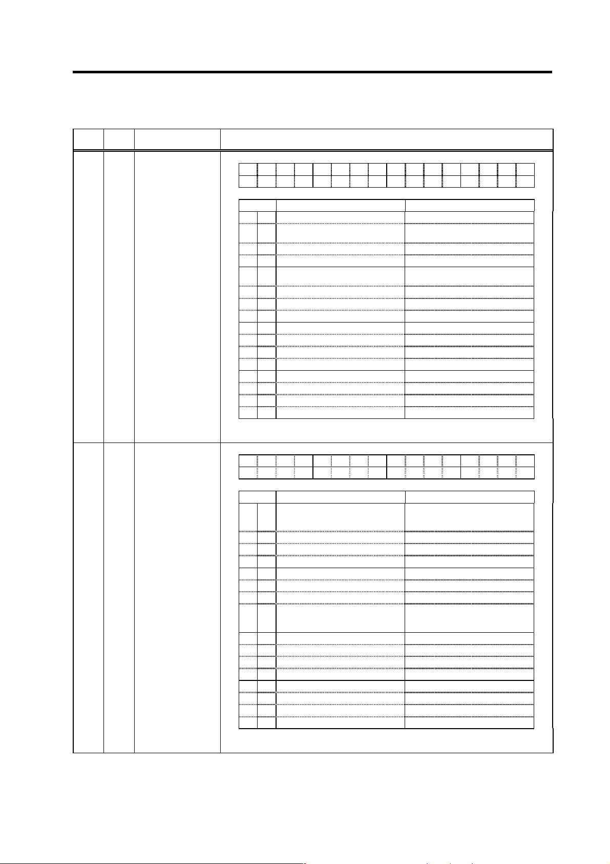
3. Setup
3 - 36
High-gain specifications
No. Abbrev. Parameter name Explanation
F E D C B A 9 8 7 6 5 4 3 2 1 0
pabs rabs
bit Meaning when "0" is set Meaning when "1" is set
0
1 rabs
Normal setting Rotary axis machine end absolute
position control
2
3
4
pabs
Normal setting Speed/current synchronous
control absolute position control
5
6
7
8
9
A
B
C
D
E
F
(Note) Set to "0" for bits with no particular description.
SV081 SPEC2*
Servo specification
selection 2
F E D C B A 9 8 7 6 5 4 3 2 1 0
obshj lmc3 lmct
bit Meaning when "0" is set Meaning when "1" is set
0 lmct
Setting for normal use Lost motion compensation 3
adjustment time measurement
valid
1 lmc3
Lost motion compensation 3 stop Lost motion compensation 3 start
2
3
4
5
6
7 obshj
Normal use Disturbance observer
High-load inertia compatible
control
8
9
A
B
C
D
E
F
(Note) Set to "0" for bits with no particular description.
SV082 SSF5
Servo function
selection5
Parameters with an asterisk * in the abbreviation, such as PC1*, are validated with the NC power turned ON again.
3. Setup
3 - 37
High-gain specifications
No.
Abbrev.
Parameter name Explanation
Setting
range (Unit)
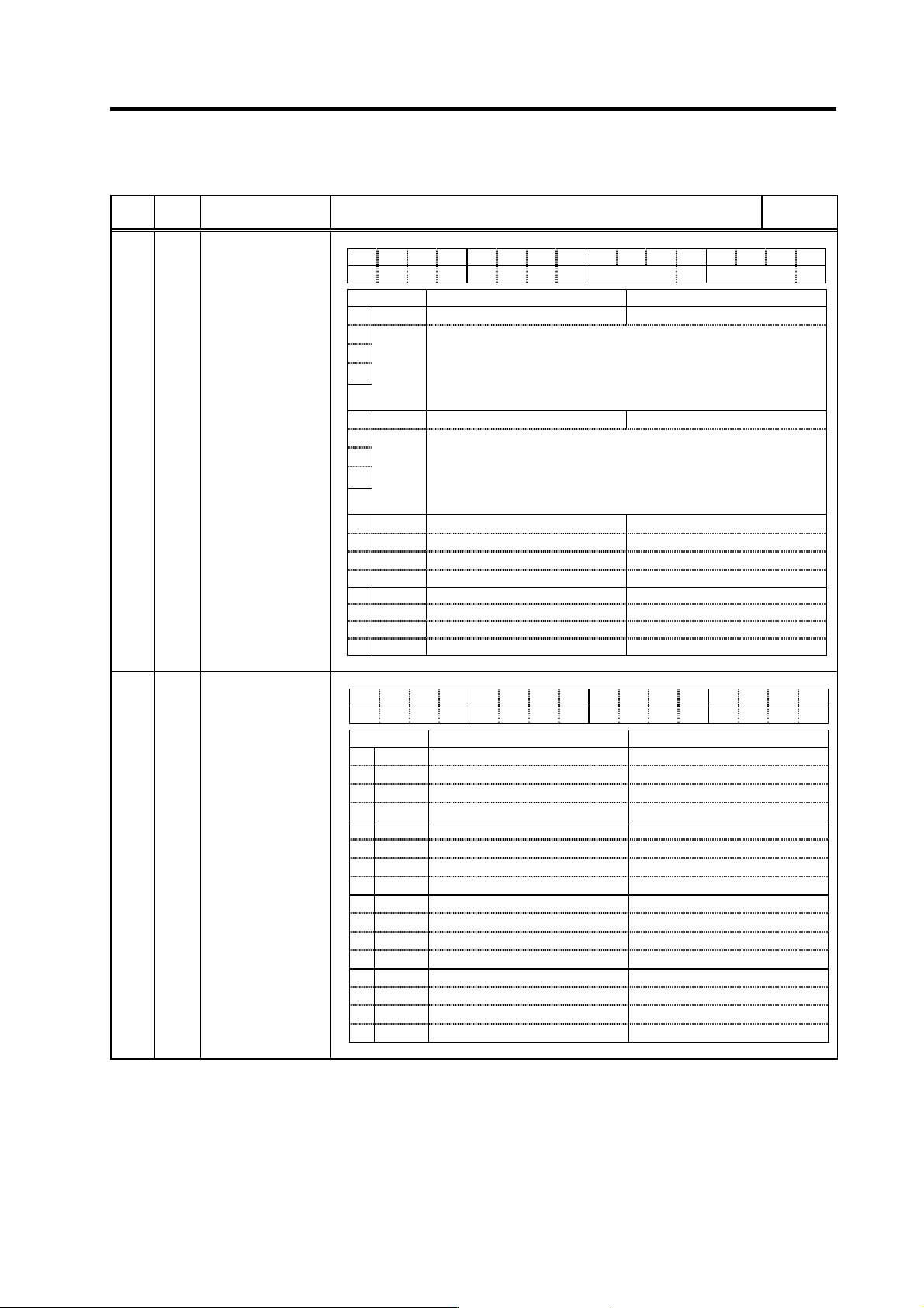
F EDCBA98765 4 3 2 10
nfd5 nfd4
bit Meaning when set to 0 Meaning when set to 1
0
1 Set the filter depth for Notch filter 4 (SV038).
2
Setting value Deep ← → Shallow
3 000 001 010 011 100 101 110 111
nfd4
Depth (dB)
-
∞
-18.1 -12.0 -8.5 -6.0 -4.1
-2.5 -1.2
4
5 nfd5 Set the filter depth for Notch filter 5 (SV046).
6
Setting value Deep ← → Shallow
7
000 001 010 011 100 101 110 111
Depth (dB) -∞ -18.1 -12.0 -8.5 -6.0 -4.1
-2.5 -1.2
8
9
A
B
C
D
E
F
SV083 SSF6
Servo function
selection 6
(Note) Set to "0" for bits with no particular description.
F E D C B A 9 8 7 6 5 4 3 2 1 0
bit Meaning when set to 0 Meaning when set to 1
0
1
2
3
4
5
6
7
8
9
A
B
C
D
E
F
SV084 SSF7
Servo function
selection 7
(Note) Set to "0" for bits with no particular description.