bnp-b2365(eng)b.pdf - 第82页
2. Wiring and Connection 2 - 43 2-7-2 Spindle coil changeover There are spindle motors capable of coil changeover control, which enables favorable characteristics to be attained from low speeds to high speeds by changing…
2. Wiring and Connection
2 - 42
2-7 Peripheral control wiring
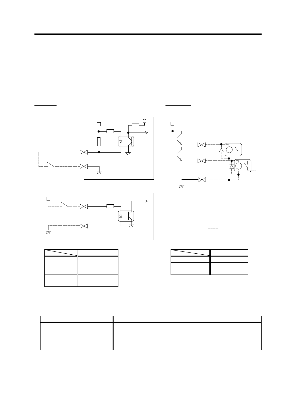
2-7-1 Input/output circuit wiring
The input/output circuit to control the external signal such as external emergency stop input and relay
changeover signal output is wired.
The input/output circuit for each unit is as follows.
Input circuit Output circuit
For a switch or relay to be wired, use a switch or relay that satisfies the input/output (voltage, current)
conditions.
Interface name Selection example
For digital input signal (CN23,CN9)
Use a minute signal switch which is stably contacted and operated even with low
voltage or current
<Example> OMRON: G2A, G6B type, MY type, LY type
For digital output signal (CN9)
Use a compact relay operated with rating of 24VDC, 50mA or less.
<Example> OMROM: G6B type, MY type
Input condition
Output condition
Output voltage 24VDC ±5%
Switch ON
18VDC to 25.2VDC
9mA or more
Tolerable output
current Io
50mA or less
Switch OFF
4VDC or less
2mA or less
20
10
CN9 connector
Servo/spindle
drive unit
Switch
33.3k
24V
10k
1
3
CN23 connector
Power supply unit
Switch
24V
2k
Servo/spindle
drive unit
8
10
CN9 connector
18
MPO1
MPO2
MPI1
24G
24G
Relay, etc.
24V
The part indicated by the " " must be prepared
by the user.
2. Wiring and Connection
2 - 43
2-7-2 Spindle coil changeover
There are spindle motors capable of coil changeover control, which enables favorable characteristics to
be attained from low speeds to high speeds by changing two types or three types (only for
MDS-C1-SPM) of coils.
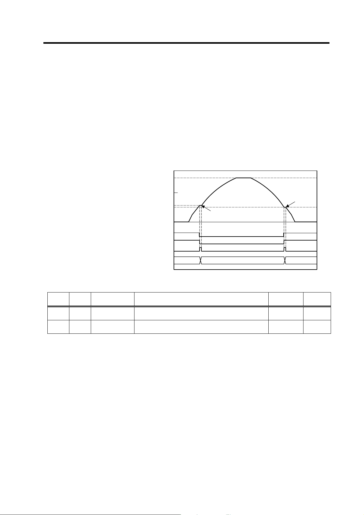
(1) Coil changeover control
The speed at which to change the coils is detected by the spindle drive according to the value set
with spindle parameter SP020. This is conveyed to the NC with a speed detection (SD) signal. The
NC judges the other conditions (coil fixed, etc.), and issue a coil changeover command to the
spindle drive with the L coil selection command (LCS).
To prevent the contactor from varying, the hysteresis set with SP047 is applied on the speed when
changing from the low-speed coil to the high-speed coil and the high-speed coil to the low-speed
coil.
Speed detection (SD1) [SP→NC]
L coil selection command (LCS) [NC→SP]
Changing coil (MKC) [SP→NC]
Contactor changeover
0
2000
Time
6000
Spindle motor speed
(r/min)
Low-speed coil
4000
(SP020+SP047
High-speed coil
Low-speed coil
SP020
Spindle motor coil changeover control
No. Abbrev. Parameter name Description Setting range
Standard
value
SP020 SDTS* Speed detection
set value
Set the motor speed of which speed detection 1 output is
performed. Usually, the setting value is 10% of SP017 (TSP).
0 to 32767
(r/min)
600
SP047 SDTR* Speed detection
reset value
Set the reset hy steresis width for a speed detection set value
defined in SP020 (SDTS).
0 to 1000
(r/min)
30
2. Wiring and Connection
2 - 44
(2) Protective functions
[1] Base shutoff after a winding changeover
When the L-coil selection command (LCS) is used to perform low-speed winding → high-speed
winding switching, or vice-versa, the base is shut off during contactor operation time in order to
protect the spindle drive unit's main circuit. The base shutoff time is determined by the "Winding
changeover base shutoff timer" (SP059) setting. The standard time setting should be used, as a
shorter time can cause contactor burn damage.
(Refer to 5-2-2 (4) "Spindle control output 4" Coil changing (bit 6) for details.)
No. Abbrev. Parameter name Description Setting range
Standard
value
SP059 MKT* Winding
changeover base
shut-off timer
Set the base shut-off time for contactor switching at coil
changeover.
Note that the contactor may be damaged with burning if the
value of this parameter is too small.
50 to 10000
(ms)
150
[2] Current limit after coil changeover
Following a coil changeover, the current is limited (SP061) for the period specified by the current
limit timer (SV060) in order to stabilize control. Because position loop control (synchronous tap,
C-axis control, etc.) that occurs immediately after a coil changeover will result in unstable control,
be sure that position commands specified by the sequence is input after the current limit is
cancelled.
No. Abbrev. Parameter name Description Setting range
Standard
value
SP060 MKT2* Current limit timer
after coil
changeover
Set the current limit time to be taken after completion of
contactor switching at coil changeover.
0 to 10000
(ms)
500
SP061 MKIL* Current limit value
after coil
changeover
Set the current limit value during a period defined in SP060
(MKT2) after completion of contactor switching at coil
changeover.
0 to 120 (%) 75