bnp-b2365(eng)b.pdf - 第224页
4. Servo Adjustment 4 - 25 (3) Adjusting the lost motion compensa tion timing If the speed loop gain has been lo wered from the standard setting value because th e machine rigidity is low or because machine reso nance oc…
4. Servo Adjustment
4 - 24
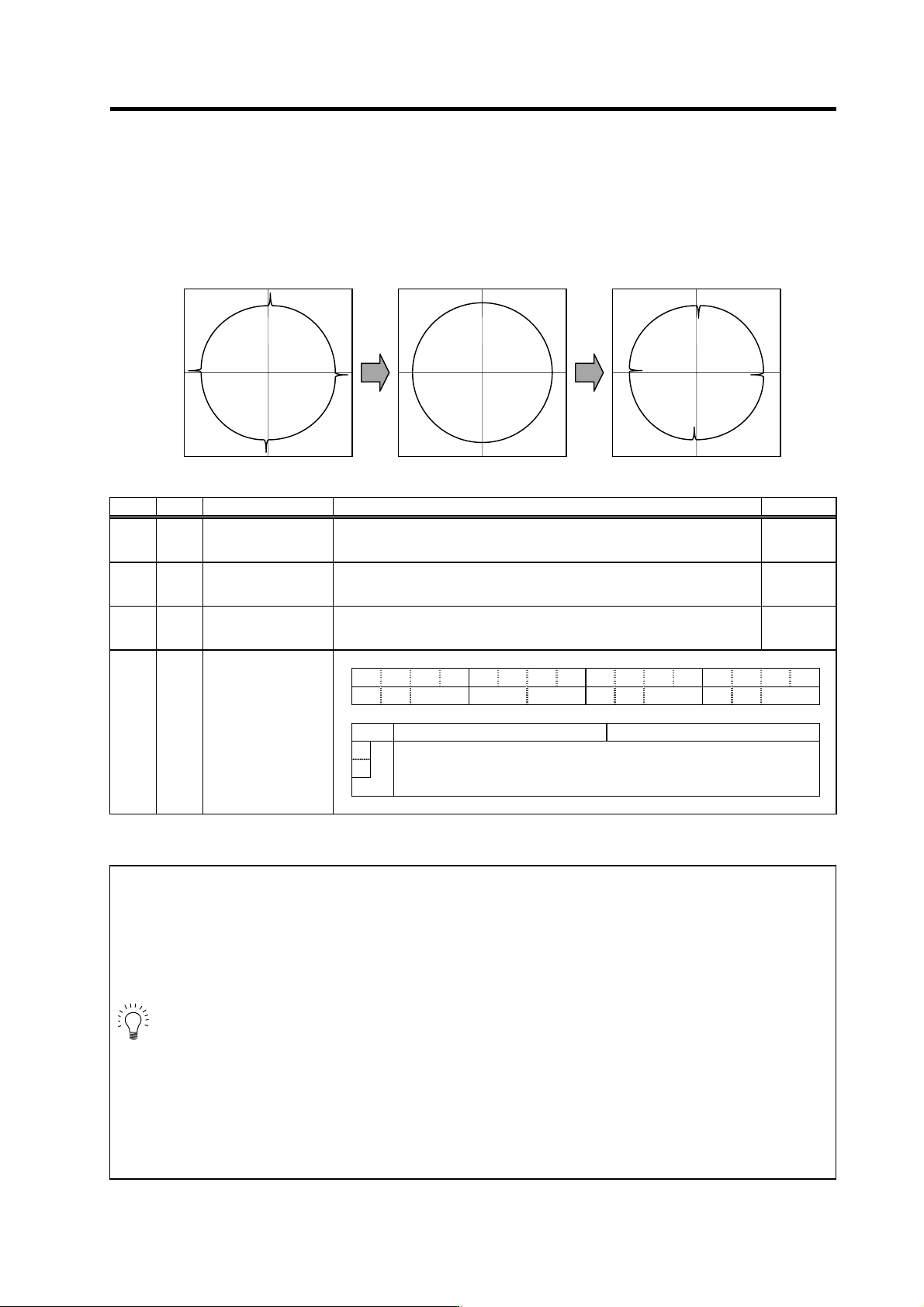
<Adjustment method>
Perform the final adjustment, carrying out the NC sampling measurement (DBB measurement) or
actual cutting. If the compensation amount is insufficient, increase LMC1 or LMC2 by 5% at a time.
Note that if the setting is too high, biting may occur.
No. Abbrev. Parameter name Explanation Setting range
SV016 LMC1 Lost motion
compensation 1
Set the compensation amount based on the stall (rated) current of the motor.
The standard setting is double of the friction torque. Setting to "0" means the
compensation amount is zero.
-1 to 200
(Stall [rated]
current %)
SV041 LMC2 Lost motion
compensation 2
Set this with SV016 (LMC1) only when you wish to set the lost motion
compensation amount to be different depending on the command directions.
Set to "0" as a standard.
-1 to 200
(Stall [rated]
current %)
SV032 TOF Torque offset This setting is specified when using lost motion compensation.
Set the unbalance torque of vertical axis and inclined axis.
-100 to 100
(Stall [rated]
current %)
F E D C B A 9 8 7 6 5 4 3 2 1 0
aflt zrn2 afse ovs lmc omr zrn3 vfct upc vcnt
bit Meaning when "0" is set Meaning when "1" is set
8 Set the compensation amount with SV016 (LMC1) and SV041 (LMC2).
9
lmc
00: Lost motion compensation stop 10: Lost motion compensation type 2
01: Lost motion compensation type 1 11: Setting prohibited
SV027 SSF1
Servo function
selection 1
POINT
1. Set SV082/bit1=0 when using LMC compensation type 2.
2. When either parameter SV016: LMC1 or SV041: LMC2 is set to 0, the same
amount of compensation is carried out in both the positive and negative direction
with the setting value of the other parameter (the parameter not set to 0).
3. When the protrusion amount varies according to direction, use LMC2 to adjust it.
For compensation in one direction only, set "-1" at the parameter (LMC1 or LMC2)
for the direction in which compensation is prohibited.
4. Even if a TOF is set, the motor's torque output characteristics and the load current
displayed at the NC servo monitor will remain unchanged. Only the LMC
compensation is affected.
5. The value set based on the friction torque is the standard value for LMC
compensation. The optimum compensation value changes with the cutting
conditions (cutting speed, cutting radius, blade type, workpiece material, etc.). Be
sure to ultimately make test cuts matching the target cutting and determine the
compensation amount.
Optimum Compensation 0 Too high
4. Servo Adjustment
4 - 25
(3) Adjusting the lost motion compensation timing
If the speed loop gain has been lowered from the standard setting value because the machine
rigidity is low or because machine resonance occurs easily, or when cutting at high speeds, the
quadrant protrusion may appear later than the quadrant changeover point on the servo control. In
this case, suppress the quadrant protrusion by setting the lost motion compensation timing
(SV039: LMCD) to delay the LMC compensation.
<Adjustment method>
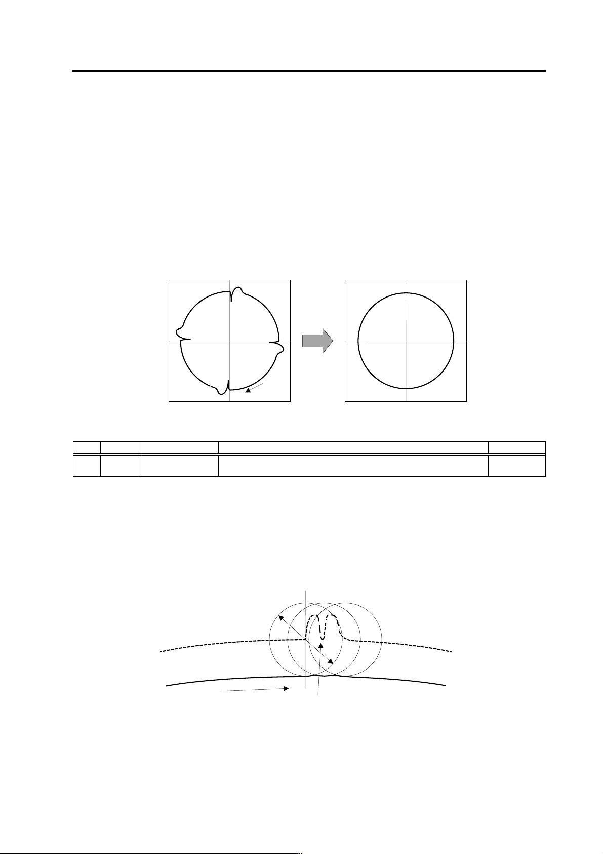
If a delay occurs in the quadrant protrusion in the circle or arc cutting as shown below in respect to
the cutting direction when CNC sampling measurement (DBB measurement) or actual cutting is
carried out, and the compensation appears before the protrusion position, set the lost motion
compensation timing (SV039: LMCD).
While measuring the arc path, increase LMCD by 10 ms at a time, to find the timing that the
protrusion and compensation position match.
Before timing delay compensation After timing delay compensation
No. Abbrev. Parameter name Explanation Setting range
SV039 LMCD Lost motion
compensation timing
Set this when the lost motion compensation timing does not match. Adjust
while increasing the value by 10 at a time.
0 to 2000
(ms)
When the LMCD is gradually raised, a two-peaked contour may occur at the motor FB position
DBB measurement. However, due to the influence of the cutter diameter in cutting such as end
milling, the actual cutting surface becomes smooth.
Because satisfactory cutting can be achieved even if this two-peaked contour occurs, consider the
point where the protrusion becomes the smallest and finest possible without over compensating
(bite-in) as the optimum setting.
Cutter center path
A
ctual cutting surface
Cutting direction
Quadrant changeover point
Point of LMC compensation execution
Cutter diameter
A
fter
compensation
Cutting
direction
4. Servo Adjustment
4 - 26
(4) Adjusting for feed forward control
In LMC compensation, a model position considering the position loop gain is calculated based on
the position command sent from the CNC, and compensation is carried out when the feed changes
to that direction. When the CNC carries out feed forward (fwd) control, overshooting equivalent to
the operation fraction unit occurs in the position commands, and the timing of the model position
direction change may be mistaken. As a result, the LMC compensation timing may deviate, or
compensation may be carried out twice or more.
If feed forward control is carried out and the compensation does not operate correctly, adjust with
the non-sensitive band (SV040 (LMCT)) during feed forward control. In this non-sensitive band
control, the overshooting set with LMCT is ignored during feed forward control. Instead the model
position direction change point is correctly recognized to correctly compensate LMC.
This parameter is meaningless when feed forward control is not being carried out.
<Adjustment method>
If the compensation timing deviates during feed forward control, increase the LMCT setting by 1µm
at a time.
Note that 2µm are set even when the LMCT is set to 0.
No. Abbrev. Parameter name Explanation Setting range
SV040 LMCT
Lost motion
compensation
non-sensitive band
Set the non-sensitive band of the lost motion compensation in the feed
forward control.
When "0" is set, the actual value that is set is 2µm. Adjust by increasing by
1µm at a time.
0 to 100
(µm)