bnp-b2365(eng)b.pdf - 第187页
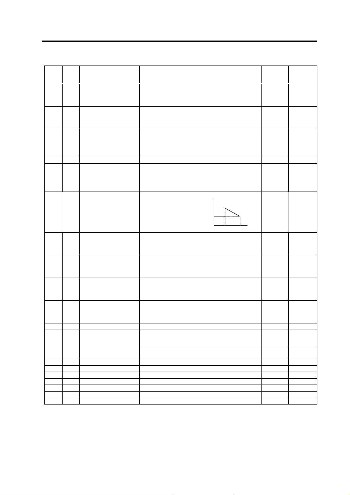
3. Setup 3 - 100 No. Abbr. Parameter name Details Setting rang e (Unit) Standard setting <For MDS-C1-SP/SPH/SPM> Set to reduce the noise generated from the spindle motor Set the band of the low path filter 0 to 225…
3. Setup
3 - 99
No. Abbr. Parameter name Details
Setting
range
(Unit)
Standard
setting
SP194 VGTP*
Synchronized tapping
control
speed loop gain
proportional term
Set the speed loop proportional gain in synchronized
tapping control mode.
0 to 1000 63
SP195 VGTI*
Synchronized tapping
control
speed loop gain integral
term
Set the speed loop integral gain in synchronized tapping
control mode.
0 to 1000 60
SP196 VGTD*
Synchronized tapping
control
speed loop gain delay
advance
term
Set the speed loop delay advance gain in synchronized
tapping control mode.
When this parameter is set to "0", PI control is applied.
0 to 1000 15
SP197 Fixed control constant Set by Mitsubishi. Set "0" unless designated in particular. 0 0
SP198 VCGT*
Synchronized tapping
control
target value of variable
speed loop proportional
gain
Set the magnification of speed loop proportional gain with
respect to SP194 (VGTP) at the maximum motor speed
defined in SP017 (TSP) in synchronized tapping control
mode.
0 to 100 (%) 100
SP194
SP194×
(SP198/100)
SP199 VCST*
Synchronized tapping
control
change starting speed of
variable speed loop
proportional gain
Set the speed where
the speed loop
proportional gain
change starts during
synchronized tapping
control.
0 SP199 SP017
0 to 32767
(r/min)
0
SP200 FFCI*
Synchronized tapping
control
acceleration feed forward
gain (gear 1)
Set the acceleration feed forward gain for selection of
gear 000 during synchronized tapping control.
This parameter should be used when an error of relative
position to Z-axis servo is large.
0 to 1000
(%)
0
SP201 FFC2*
Synchronized tapping
control
acceleration feed forward
gain (gear 2)
Set the acceleration feed forward gain for selection of
gear 001 during synchronized tapping control.
0 to 1000
(%)
0
SP202 FFC3*
Synchronized tapping
control
acceleration feed forward
gain (gear 3)
Set the acceleration feed forward gain for selection of
gear 010 during synchronized tapping control.
0 to 1000
(%)
0
SP203 FFC4*
Synchronized tapping
control
acceleration feed forward
gain (gear 4)
Set the acceleration feed forward gain for selection of
gear 011 during synchronized tapping control. 0 to 1000
(%)
0
SP204 THOD Fixed control constant Set by Mitsubishi. Set "0" unless designated in particular. 0 0
<For MDS-C1-SPM>
This validates the PLG Z-phase automatic adjustment
function
0 to 1
0 → 1
SP205
ZCHS
PLG Z-phase automatic
adjustment
<For MDS-C1-SP/SPH/SPX/SPHX>
Not used. Set to "0".
0 0
SP206 GCK* Fixed control constant Set by Mitsubishi. Set "0" unless designated in particular. 0 0
SP207 GDL* Fixed control constant Set by Mitsubishi. Set "0" unless designated in particular. 0 0
SP208 W2 Fixed control constant Set by Mitsubishi. Set "0" unless designated in particular. 0 0
SP209 Not used. Set to "0". 0 0
SP210 Not used. Set to "0". 0 0
SP211 Not used. Set to "0". 0 0
SP212 Not used. Set to "0". 0 0
Parameters with an asterisk * in the abbreviation, such as OSP*, are validated with the NC power turned ON again.
3. Setup
3 - 100
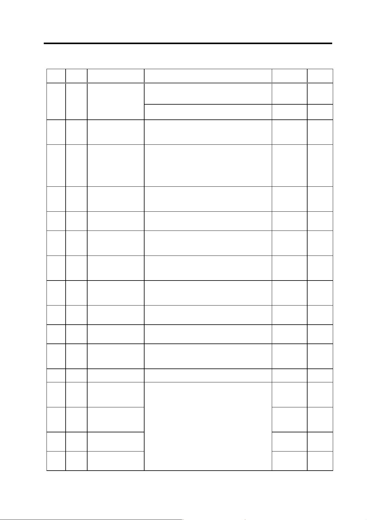
No. Abbr. Parameter name Details
Setting range
(Unit)
Standard
setting
<For MDS-C1-SP/SPH/SPM>
Set to reduce the noise generated from the spindle motor
Set the band of the low path filter
0 to 2250
(rad/s)
0
SP213 LPF
Low path filter
<For MDS-C1-SPX/SPHX>
Not used. Set to "0".
0 0
SP214 TZRN
Synchronized tapping
control
zero point return speed
This parameter is valid when SP193 (SPECT)/bit E is set
to "0".
Set the zero point return speed used when the speed loop
changes to the position loop.
0 to 500
(r/min)
50
SP215 TPDT
Synchronized tapping
control
zero point return
deceleration rate
This parameter is valid when SP193 (SPECT)/bit E is set
to "0".
Set the deceleration rate where the machine starts to
decelerate when it returns to the target stop point during
synchronized tapping zero point return.
When the machine tends to overshoot at the stop point
set a smaller value.
0 to 10000
(pulse)
1
SP216 TPST
Synchronized tapping
control
zero point return shift
amount
This parameter is valid when SP193 (SPECT)/bit E is set
to "0".
Set the synchronized tapping zero point position.
0 to 4095 0
SP217 TINP
Synchronized tapping
control
in-position width
Set the position error range for output of the in-position
during synchronized tapping control.
1 to 2880
(1/16 deg)
16
SP218 TODR*
Synchronized tapping
control
excessive error width
Set the excessive error width during synchronized
tapping.
0 to 32767
(pulse)
(1 pulse =
0.088 deg)
32767
SP219 IQGT*
Synchronized tapping
control
current loop gain
magnification 1
Set the magnification of current loop gain (torque
component) during synchronized tapping control.
1 to 1000 (%) 100
SP220 IDGT*
Synchronized tapping
control
current loop gain
magnification 2
Set the magnification of current loop gain (excitation
component) during synchronized tapping control.
1 to 1000 (%) 100
SP221 PG2T
Synchronized tapping
control
position loop gain 2
Set the second position loop gain when high-gain control
is applied during synchronized tapping control.
When this parameter is not used, set to "0".
0 to 999
(rad/s)
0
SP222 PG3T
Synchronized tapping
control
position loop gain 3
Set the third position loop gain when high-gain control is
applied during synchronized tapping control.
When this parameter is not used, set to "0".
0 to 999
(rad/s)
0
SP223 SPDV Speed monitor speed
Set the spindle limit speed in the door open state.
(Invalid when 0 is set.)
If the spindle end speed exceeds this setting value when
the door is open, the speed monitor error (5E) will occur.
0 to 800
(r/min)
0
SP224 SPDF Speed monitor time
Set the time (continuous) to detect alarms.
(Detected instantly when 0 is set.)
0 to 2813
(3.5 ms)
0
SP225 OXKPH
Position loop gain
magnification after
orientation completed
(H coil)
0 to 2560
(1/256-fold)
0
SP226 OXKPL
Position loop gain
magnification after
orientation completed
(L coil)
0 to 2560
(1/256-fold)
0
SP227 OXVKP
Speed loop proportional
gain magnification after
orientation completed
0 to 2560
(1/256-fold)
0
SP228 OXVKI
Speed loop cumulative
gain magnification after
orientation completed
If gain changeover is valid (SP097: SPEC0/bitC=1) during
orientation control, set the magnification of each gain
changed to after orientation completed.
0 to 2560
(1/256-fold)
0
Parameters with an asterisk * in the abbreviation, such as OSP*, are validated with the NC power turned ON again.
3. Setup
3 - 101
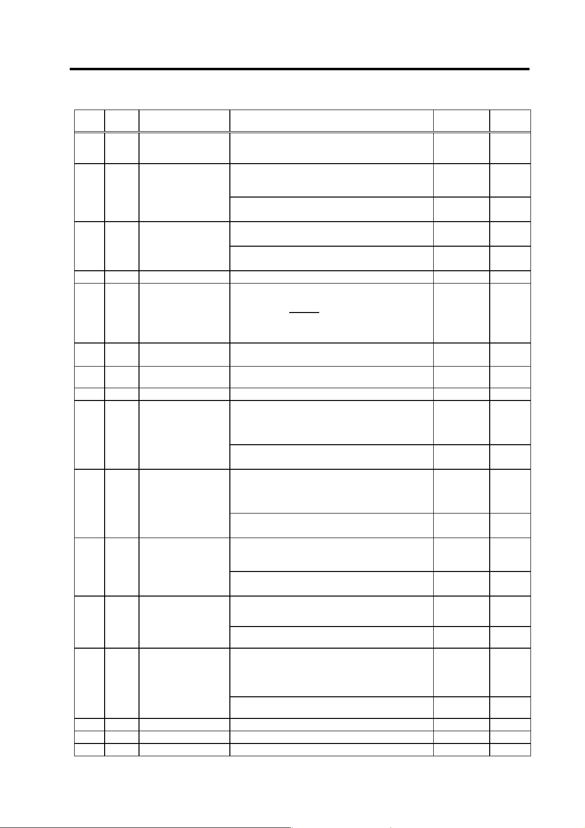
No. Abbr. Parameter name Details
Setting range
(Unit)
Standard
setting
SP229 OXSFT
Orientation virtual target
shift amount
Set the amount to shift the target position when
orientation virtual target position is valid (SP097:
SPEC0/bitD=1).
0 to 2048
(360 deg/4096)
0
<For MDS-C1-SPH>
Set the ratio of iron loss to all losses when temperature
compensation considering iron loss is valid.
0 to 100
(%)
0
SP230
WIH
Iron loss compensation
value
<For MDS-C1-SP/SPX/SPHX/SPM>
Not used. Set "0".
0 0
<For MDS-C1-SPH>
Set the primary-delay time constant to detect overload 2
0 to 60
(min)
0
SP231
OL2T Overload 2 time constant
<For MDS-C1-SP/SPX/SPHX/SPM>
Not used. Set "0".
0 0
SP232 Not used. Set "0". 0 0
SP233 JL*
Disturbance observer
Load inertia rate
Set "the motor inertia + motor axis conversion load inertia"
in respect to the motor inertia.
SV037 (JL) =
Jl + Jm
Jm
× 100
Jm : Motor inertia
Jl : Motor axis conversion load inertia
0 to 5000 (%) 0
SP234 OBS1*
Disturbance observer
low path filter frequency
Set the frequency of the low path filter for when the
disturbance observer is valid.
0 to 1000
(rad/s)
0
SP235 OBS2*
Disturbance observer
gain
Set the gain for the disturbance observer.
0 to 500 (%) 0
SP236 OBS3 Fixed control constant Set by Mitsubishi. Set "0" unless designated in particular. 0 0
<For MDS-C1-SPM>
The following value is judgment value for spindle speed
overrun (alarm 3E).
The speed command + SP237 × 0.125 [r/min]
0 to 32767
(r/min)
0
SP237
KSCP*
Spindle speed overrun
judgment value
<For MDS-C1-SP/SPH/SPX/SPHX>
Not used. Set "0".
0 0
<For MDS-C1-SPM>
The following value is judgment value for speed excessive
deflection 2 (alarm 3F).
The speed command × SP238 / 100 [r/min]
0 to 100
(%)
0
SP238
SE2R
Speed excessive
deflection 2
detection range
<For MDS-C1-SP/SPH/SPX/SPHX>
Not used. Set "0".
0 0
<For MDS-C1-SPM>
Set the continuous detection time for speed excessive
deflection 2 (alarm 3F).
0 to 3000 0
SP239
SE2T
Speed excessive
deflection 2
detection time
<For MDS-C1-SP/SPH/SPX/SPHX>
Not used. Set "0".
0 0
<For MDS-C1-SPX/SPHX>
This validates the automatic adjustment function for the
PLG connected to the MDS-B-PJEX.
0 to 1
0 → 1
SP240 EXHS
PLG automatic
adjustment (PJEX)
<For MDS-C1-SP/SPH/SPM>
Not used. Set "0".
0 0
<For MDS-C1-SPX/SPHX>
This changes the spindle drive unit type, serial NO. and
software version display.
"0" Displays the details for the spindle drive unit.
"1" Displays the details for the detector converter.
0 to 1 0
SP241 EXBIT
Spindle monitor
changeover
<For MDS-C1-SP/SPH/SPM>
Not used. Set "0".
0 0
SP242 Vavx Fixed control constant Set by Mitsubishi. Set "0" unless designated in particular. 0 0
SP243 UTTM Fixed control constant Set by Mitsubishi. Set "0" unless designated in particular. 0 0
SP244 OPLP Fixed control constant Set by Mitsubishi. Set "0" unless designated in particular.
Parameters with an asterisk * in the abbreviation, such as OSP*, are validated with the NC power turned ON again.