bnp-b2365(eng)b.pdf - 第73页
2. Wiring and Connection 2 - 34 2-5-1 Power supply input connection (1) When using one pow er supply unit Install the drive unit so that the DC power supply bus (L+, L-) is as near to the power supply unit as possible. L…

2. Wiring and Connection
2 - 33
2-5 Connection of power supply
CAUTION
1. Make sure that the power supply voltage is within the specified range of each
unit. Failure to observe this could lead to damage or faults.
2. For safety purposes, always install a No-fuse breaker (NFB), and make sure
that the circuit is cut off when an error occurs or during inspections.
3. The wire size will differ according to each drive unit capacity.
4. For safety purposes, always install a magnetic contactor (contactor) on the
main circuit power supply input. Large rush currents will flow when the power
is turned ON.
5. A semiconductor element is used in the power supply unit's magnetic contact
drive circuit, and a surge absorber is installed to protect the element.
Therefore, a leakage current of approx. 15mA is passed. Confirm that the
exciting coil in the magnetic contact will not function at 15mA or less.
2. Wiring and Connection
2 - 34
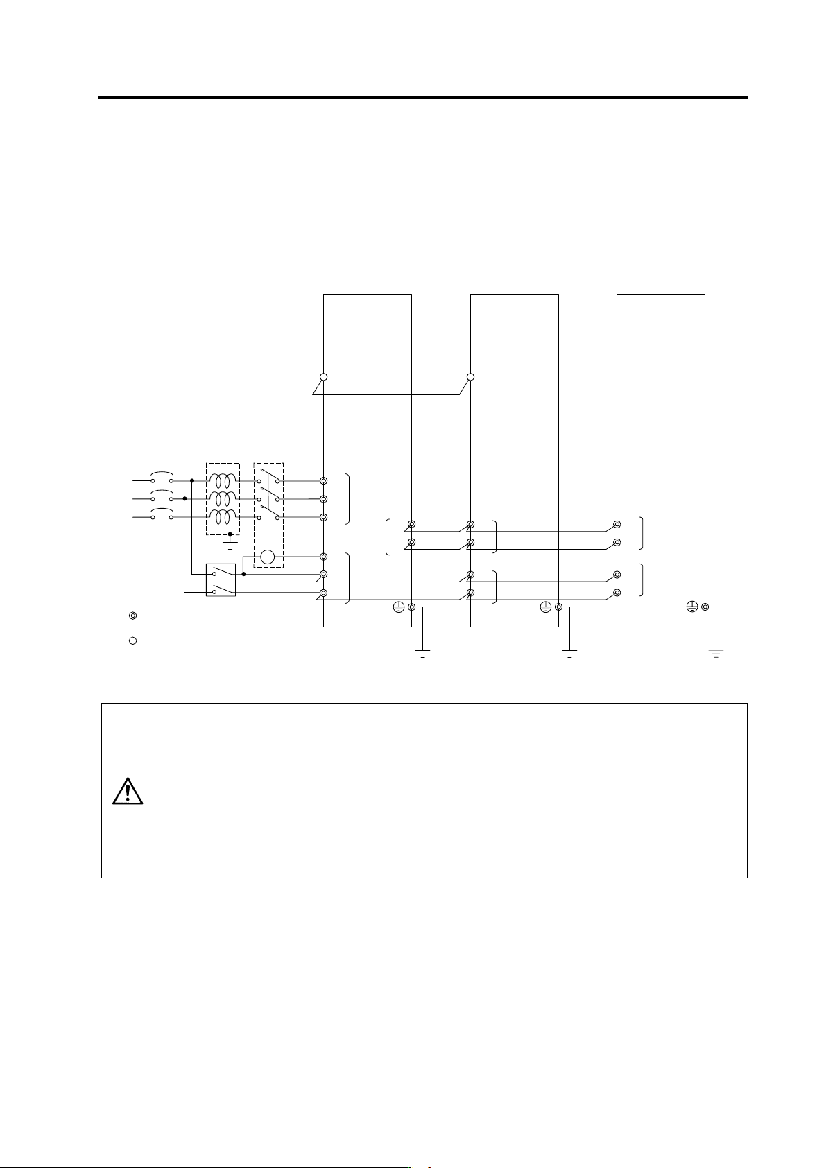
2-5-1 Power supply input connection
(1) When using one power supply unit
Install the drive unit so that the DC power supply bus (L+, L-) is as near to the power supply unit as
possible. Large-capacity spindle drive units, in particular, should be installed adjacent to the power
supply unit which they control.
AC
reactor
Contactor
MC1
T
S
R
No-fuse
breaker
Ground
: Main circuit
: Control circuit
CN4
L1
L2
L3
L11
TE3
TE1
L+
L-
MDS-C1-SP
MDS-C1-CV
TE3
TE2
L+
L-
L11
L21
TE2
Ground
Ground
L21
MDS-C1-V1/V2
TE3
TE2
L+
L-
L11
L21
Ground
MC
Breake
r
CN4
CAUTION
1. The power supply unit is a power supply regenerative type converter; an AC
reactor is surely installed in the power supply line.
2. When connecting to the TE3 terminal, connect to the power supply side
(primary side) of the AC reactor.
3. Connect the power supply unit's CN4 connector with the spindle drive unit of
the maximum capacity. If there is no spindle drive unit, connect to the servo
drive unit which is the unbalance axis.
4. When installing the units dispersed install the spindle drive unit adjacent to
the power supply unit, and connections for other drive units should be such
that the total TE2 wiring length is 50cm or less.
2. Wiring and Connection
2 - 35
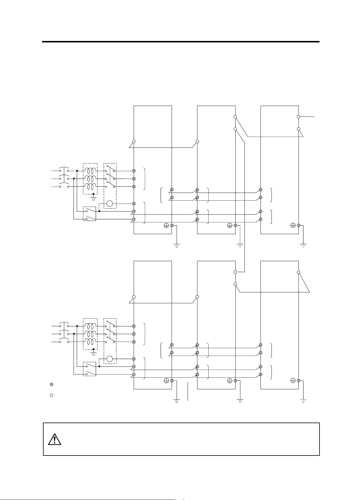
(2) When using two or more power supply units within a single NC communication bus system
Install a no-fuse breaker and a contactor for each of the power supply units.
MC1
T
S
R
Contactor
No-fuse
breake
r
Ground
CN1A
CN4
L1
L2
L3
L11
TE3
TE1
CN1B
L+
L-
MDS-C1-SPMDS-C1-CV
CN4
TE3
TE2
L+
L-
L11
L21
TE2
AC
reactor
Ground
Ground
L21
CN1A
CN1B
MDS-C1-V1/V2
TE3
TE2
L+
L-
L11
L21
Ground
To N C
MC
Breaker
MC1
T
S
R
Contactor
No-fuse
breake
r
Ground
: Main circuit
: Control circuit
CN1A
CN4
L1
L2
L3
L11
TE3
TE1
CN1B
L+
L-
MDS-C1-SPMDS-C1-CV
CN4
TE3
TE2
L+
L-
L11
L21
TE2
AC
reactor
Ground
Ground
L21
CN1A
MDS-C1-V1/V2
TE3
TE2
L+
L-
L11
L21
Ground
MC
Breaker
CAUTION
1. An AC reactor and breaker are required for each power supply unit.
2. When installing the units dispersed install the spindle drive unit adjacent to
the power supply unit, and connections for other drive units should be such
that the total TE2 wiring length is 50cm or less.