bnp-b2365(eng)b.pdf - 第127页
3. Setup 3 - 40 (2) Electronic gear related parameters The setting range of the foll owing pa rameters, whi ch configure the e lectronic gea rs, may be limited according to the combination. Refer to section "3 -4 Re…
3. Setup
3 - 39
3-3 Setting the initial parameters for the servo drive unit
(Standard specifications)
The servo parameters must be set before the servo system can be started up. The servo parameters
are input from the NC. The input method differs according to the NC being used, so refer to each NC
Instruction Manual.
3-3-1 Setting the standard parameters
When starting up the system, first set the standard parameters listed in "3-3-2 List of standard
parameters for each servomotor". For the parameters shown below, check the machine and servo
system specifications and determine the setting value.
(1) Basic specification pa rameters
[1] When performing absolute position control, set SV017/bit7=1. This may be automatically set by
NC system parameter setting, depending on NC model. (Setting on the servo parameter screen
is not valid.)
[2] For HA053N, HA13N, HA23N, HA33N motors, if the connector direction of the motor end
detector with motor power supply connector is 90°, se t SV017/bit5=1. If the angl e is 180°, use a
standard setting (SV017/bit5=0).
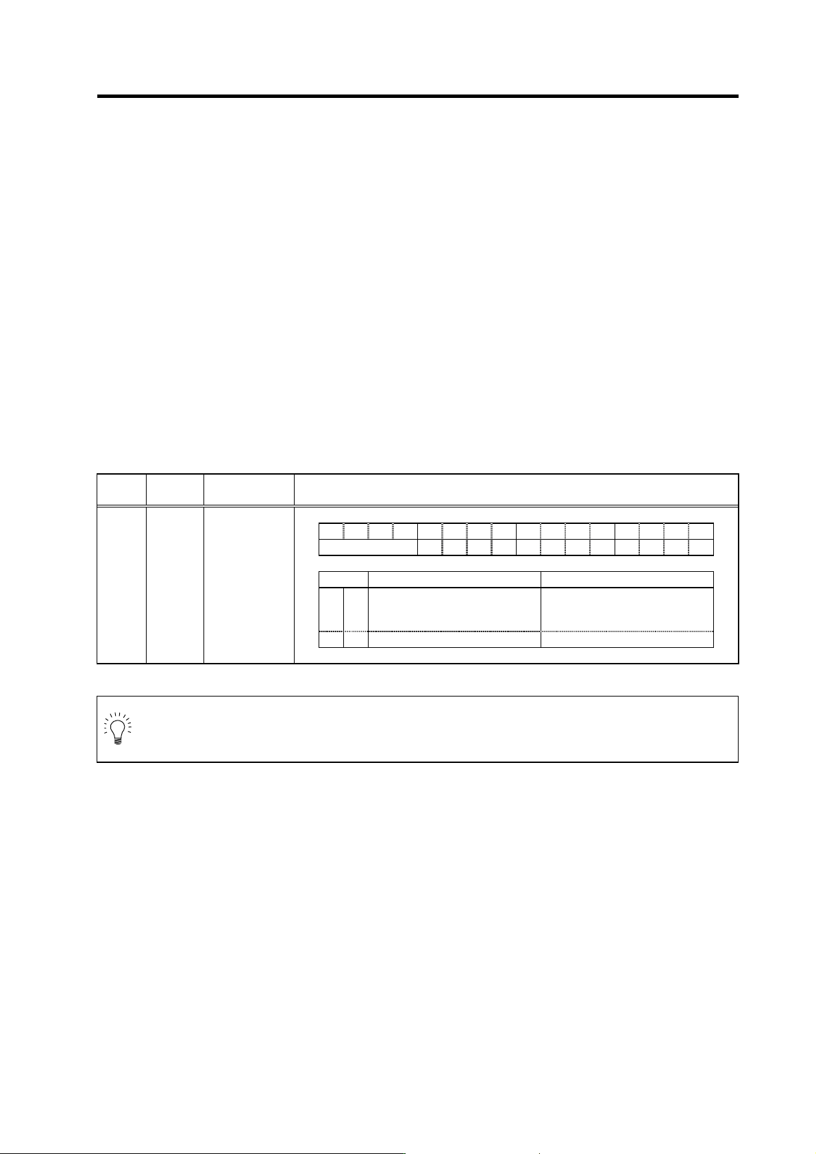
Setting basic specification parameters
Standard specifications
No. Abbrev.
Parameter
name
Explanation
F E D C B A 9 8 7 6 5 4 3 2 1 0
spm mpt mp abs vdir fdir vfb seqh dfbx
bit Meaning when set to 0 Meaning when set to 1
5 vdir
Standard setting
HA motor (4 pole motor)
Detector installation position 90
degrees (B, D)
7 abs Incremental control Absolute position control
SV017 SPEC*
Servo
specification
selection 1
POINT
Setting of absolute position control (SV017/bit7) may be set automatically by NC
system parameter setting, dependi ng on NC model. In this case, setting on the serv o
parameter screen is not valid.
3. Setup
3 - 40
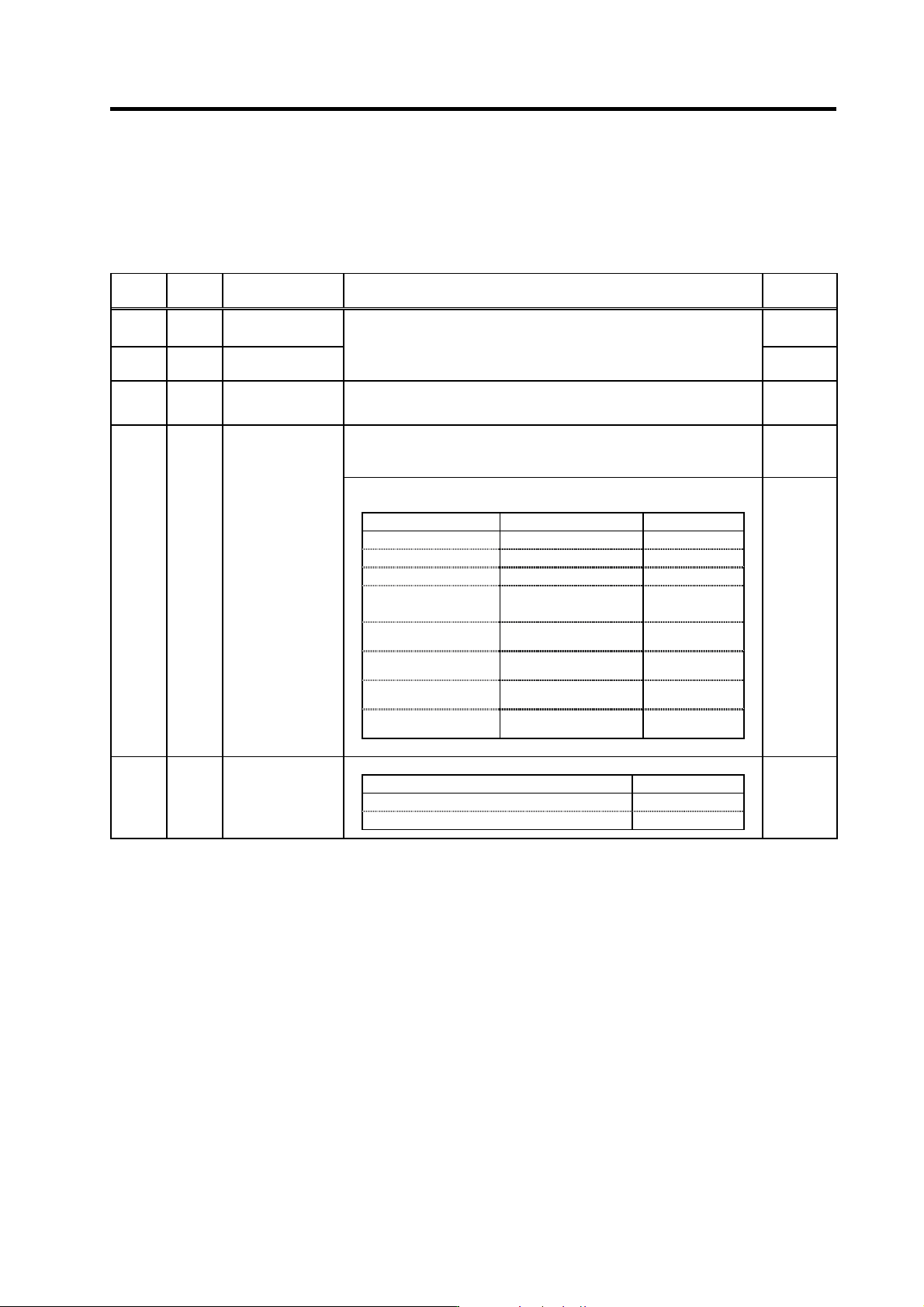
(2) Electronic gear related parameters
The setting range of the foll owing pa rameters, whi ch configure the e lectronic gea rs, may be limited
according to the combination. Refer to section "3-4 Restri ctions on servo control" for details.
Standard specifications
No. Abbrev. Parameter name Explanation
Setting
range (Unit)
SV001 PC1*
Motor side gear
ratio
1 to 32767
SV002 PC2*
Machine side gear
ratio
Set the motor side and machine side gear ratio.
For the rotary axis, set the total deceleration (acceleration) ratio.
Even if the gear ratio is within the setting range, the electronic gears may
overflow and cause an alarm.
1 to 32767
SV018 PIT*
Ball screw pitch
Set the ball screw pitch. Set to “360” for the rotary axis.
1 to 32767
(mm/rev)
In the case of the semi-closed loop control
Set the same value as SV020 (RNG2). (Refer to the explanation of
SV020.)
1 to 9999
(kp/rev)
In the case of the full-closed loop control
Set the number of pulses per ball screw pitch.
Detector model name Resolution SV019 setting
O H E 2 5 K -E T , O H A 25 K - E T 100,000 (p/rev) 100
OSE104-ET,OSA104-ET 100,000 (p/rev) 100
OSE105-ET,OSA105-ET 1,000,000 (p/rev) 1000
Relative position detection
scale
Refer to detector
specification ma nual
PIT/Resolution
(
µm)
AT41 (Mitsutoyo) 1 (µm/p)
The same as
SV018 (PIT)
AT342 (Mitsutoyo) 0.5 (µm/p)
Twice as big as
SV018 (PIT)
FME type, FLE type
(Futaba)
Refer to detector
specification ma nual
PIT/Resolution
(
µm)
MP type (Mitsubishi Heavy
Industries)
Refer to detector
specification ma nual
PIT/Resolution
(
µm)
SV019 RNG1*
Position detector
resolution
1 to 9999
(kp/pit)
Set the number of pulses per one revolution of the motor end detector.
Detector model name SV020 setting
OSE104, OSA104 100
OSE105, OSA105 1000
SV020 RNG2*
Speed detector
resolution
1 to 9999
(kp/rev)
Parameters with an asterisk * in the abbreviation, such as PC1*, are validated with the NC power turned ON again.
3. Setup
3 - 41
(3) Detector related parameters
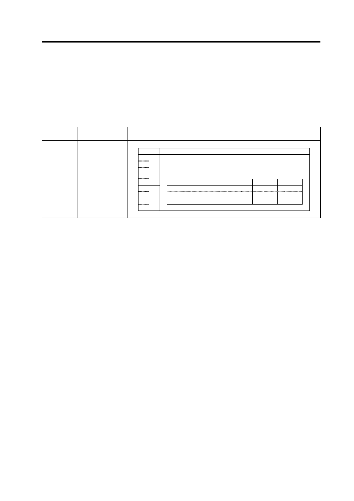
(a) For semi-closed loop control
For control using only the motor end detector, specify the settings shown in the table below. For
speed and current synchro nous control, refer to sectio n "2-4-3 Connecting the synchron ous control
system".
Setting for semi-closed loop control
Standard specifications
No.
Abbr
ev.
Parameter name
Explanation
bit Details
8
9
A
ent
Set the detector type.
Set the position detector type for “pen”, and the speed detector type
for “ent”. In the case of the semi-closed loop control, set the same
value for “pen” and “ent”.
B
Detector model pen setting ent setting
C OSE104 0 0
D OSA104 1 1
E
pen
OSE105, OSA105 2 2
F
SV025 MTYP*
Motor/Detector type
Parameters with an asterisk * in the abbreviation, such as PC1*, are validated with the NC power turned ON again.
(b) For full-closed loop control
Some parameter settings must be specified in order to use the machine end detector. These
settings are determined by type or the installation conditions of the linear scale and the ball screw
end detector.
[1] The SV025/bit8 to B (ent) setting must be specified according to the motor end detector
specifications, in the same manner as for semi-closed loop control. For current synchronous
control, however, refer to section "2-4-3 Connecting the synchronous control system".
[2] If the polarities of the motor end detector and the machine end detector do not match, specify
SV017/bit4=1 setting.
[3] To use AT342, specify SV027/bit6=1 setting.
[4] To use the MP scale, specify SV017/bit8 setting in accordance with the scale specifications.
For absolute position control, spe cify SV017/bit9=1 setting.
[5] For ABZ phase pulse output type relative position detection scale with constant Z-phase
detection position without regard to the travel direction, specify SV027/bit6=1 setting. Z-phase
detection occurs as follows: Plus-direction travel: Rising edge detection, Minus-direction
travel: Falling edge detection
[6] For machine end absolute position control at the rotation axis, specify SV081/bit1=1 setting.
[7] For speed and current synchronous control, refer to "2-4-3 Connecting the synchronous
control system".