bnp-b2365(eng)b.pdf - 第380页
Appendix 3. EMC Installation Guidelines A3 - 3 Appendix 3-3 EMC measures The main items relating to EMC measures include the following. [1] Store the device in an el ectrically sealed metal panel. [2] Earth all conductor…

Appendix 3. EMC Installation Guidelines
A3 - 2
Appendix 3-1 Introduction
EMC Instructions became mandatory as of January 1, 1996. The subject products must have a CE mark
attached indicating that the product complies with the Instructions.
As the NC unit is a component designed to control machine tools, it is believed to be out of the direct
EMC Instruction subject. However, we would like to introduce the following measure plans to backup
EMC Instruction compliance of the machine tool as the NC unit is a major component of the machine
tools.
[1] Methods for installation in control/operation panel
[2] Methods of wiring cable outside of panel
[3] Introduction of countermeasure parts
Mitsubishi is carrying out tests to confirm the compliance to the EMC Standards under the environment
described in this manual. However, the level of the noise will differ according to the equipment type and
layout, control panel structure and wiring lead-in, etc. Thus, we ask that the final noise level be
confirmed by the machine manufacturer.
These contents are the same as the EMC INSTALLATION GUIDELINES (BNP-B8582-45).
For measures for CNC, refer to "EMC INSTALLATION GUIDELINES" (BNP-B2230).
Appendix 3-2 EMC instructions
The EMC Instructions regulate mainly the following two withstand levels.
Emission ..... Capacity to prevent output of obstructive noise that adversely affects external
sources.
Immunity ..... Capacity not to malfunction due to obstructive noise from external sources.
The details of each level are classified as Table 1. It is assumed that the Standards and test details
required for a machine are about the same as these.
Table 1
Class Name Details
Generic
Standard
Standards for
determining test
and measurement
Radiated noise Electromagnetic noise radiated through the air
Emission
Conductive noise Electromagnetic noise discharged from power line
EN61000-6-4
EN61800-3
(Industrial
environment
)
EN55011
Static electricity
electrical discharge
Example) Withstand level of discharge of
electricity charged in a human body.
IEC61000-4-2
Radiated magnetic
field
Example) Simulation of immunity from digital
wireless transmitters
IEC61000-4-3
Burst immunity
Example) Withstand level of noise from relays or
connecting/disconnecting live wires
IEC61000-4-4
Conductive
immunity
Example) Withstand level of noise entering
through power line, etc.
IEC61000-4-6
Power supply
frequency field
Example) 50/60Hz power frequency noise
IEC61000-4-8
Power dip
(fluctuation)
Example) Power voltage drop withstand level
IEC61000-4-11
Immunity
Surge
Example) Withstand level of noise caused by
lightning
EN61000-6-2
EN61800-3
(Industrial
environment)
IEC61000-4-5
Appendix 3. EMC Installation Guidelines
A3 - 3
Appendix 3-3 EMC measures
The main items relating to EMC measures include the following.
[1] Store the device in an electrically sealed metal panel.
[2] Earth all conductors that are floating electrically. (Lower the impedance.)
[3] Wire the power line away from the signal wire.
[4] Use shielded wires for the cables wired outside of the panel.
[5] Install a noise filter.
Ensure the following items to suppress noise radiated outside of the panel.
[1] Securely install the devices.
[2] Use shielded wires.
[3] Increase the panel's electrical seal. Reduce the gap and hole size.
Note that the electromagnetic noise radiated in the air is greatly affected by the clearance of the panel
and the quality of the cable shield.
Appendix 3-4 Measures for panel structure
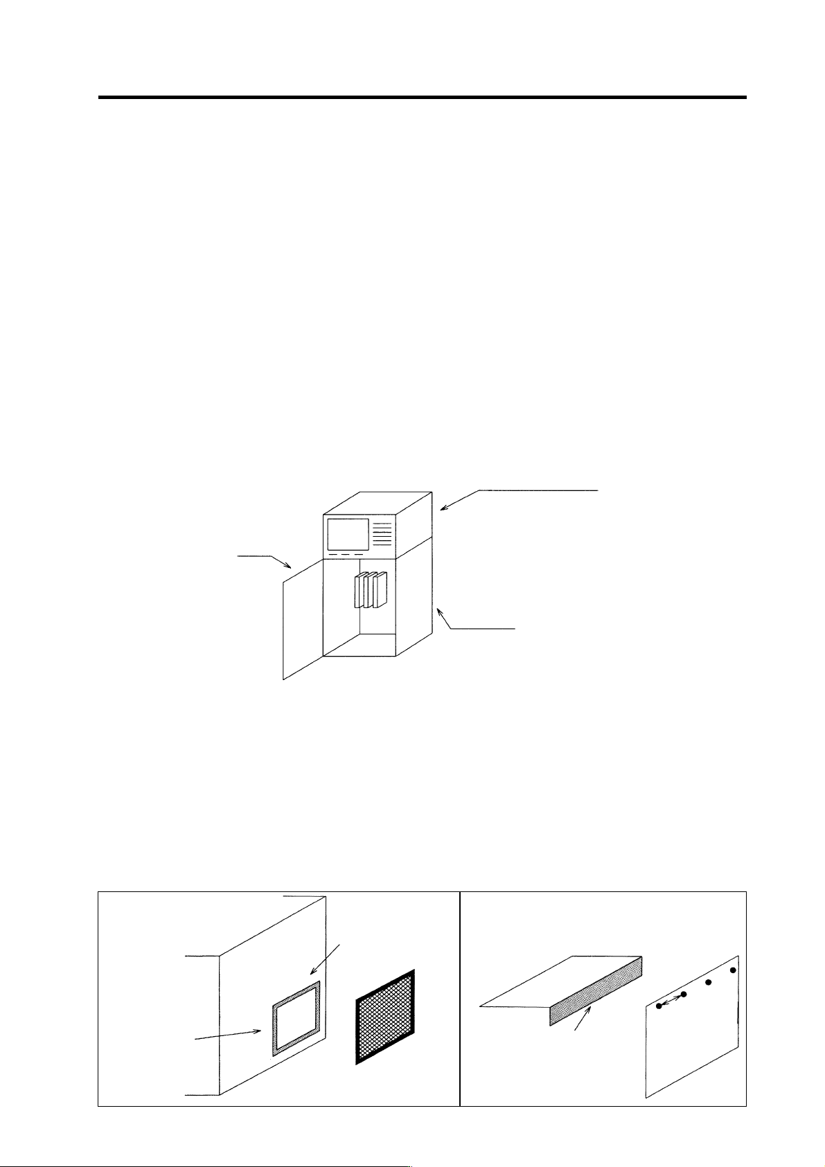
The design of the panel is a very important factor for the EMC measures, so take the following measures
into consideration.
Door
Control panel
Operation board panel
Appendix 3-4-1 Measures for control panel unit
[1] Use metal for all materials configuring the panel.
[2] For the joining of the top plate and side plates, etc., mask the contact surface with paint, and fix with
welding or screws.
In either case, keep the joining clearance to a max. of 20cm for a better effect.
[3] Note that if the plate warps due to the screw fixing, etc., creating a clearance, noise could leak from
that place.
[4] Plate the metal plate surface (with nickel, tin) at the earthing section, such as the earthing plate.
[5] The max. tolerable hole diameter of the openings on the panel surface, such as the ventilation
holes, must be 3cm to 5cm. If the opening exceeds this size, use a measure to cover it. Note that
even when the clearance is less than 3cm to 5cm, noise may still leak if the clearance is long.
Painting mask
Hole exceeding
3cm t o 5cm
∗
Provide elec t ri cal conduc tance
Painting mask
Max. joining
clearance 20cm
Exam
p
le
)
Appendix 3. EMC Installation Guidelines
A3 - 4
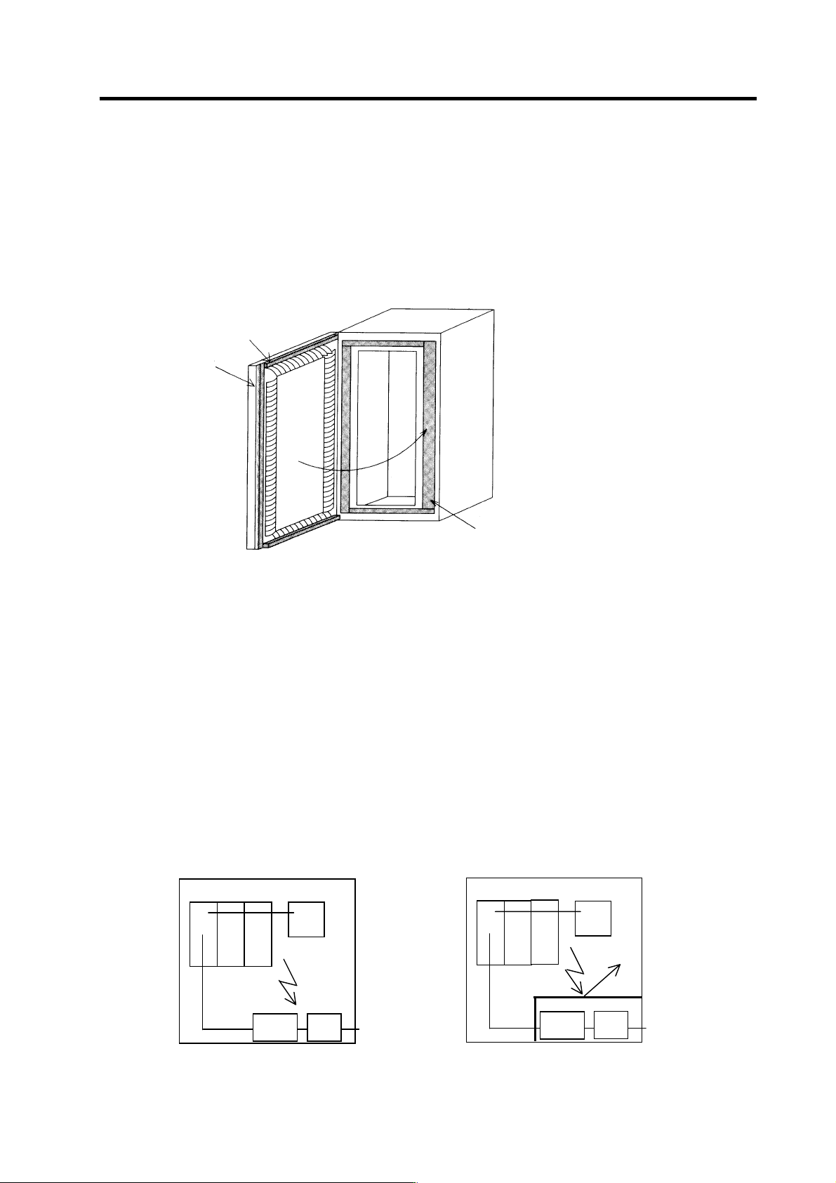
Appendix 3-4-2 Measures for door
[1] Use metal for all materials configuring the door.
[2] Use an EMI gasket or conductive packing for the contact between the door and control panel unit.
[3] The EMI gasket or conductive packing must contact at a uniform and correct position of the metal
surface of the control panel unit.
[4] The surface of the control panel unit contacted with the EMI gasket or conductive packing must
have conductance treatment.
Example) Weld (or screw) a plate that is plated (with nickel, tin).
EMI gasket
Packing
Carry out conduct ance treatment on
sections that the EMI gasket contacts.
Door
Control panel
[5] As a method other than the above, the control panel unit and door can be connected with a plain
braided wire. In this case, the panel and door should be contacted at as many points as possible.
Appendix 3-4-3 Measures for operation board panel
[1] Always connect the operation board and indicator with an earthing wire.
[2] If the operation board panel has a door, use an EMI gasket or conductive packing between the door
and panel to provide electrical conductance in the same manner as the control panel.
[3] Connect the operation board panel and control panel with a sufficiently thick and short earthing
wire.
Refer to the "EMC INSTALLATION GUIDELINES" BNP-B2230 for the NC for more details.
Appendix 3-4-4 Shielding of the power supply input section
[1] Separate the input power supply section from other parts in the control panel so that the input
power supply cable will not be contaminated by radiated noise.
[2] Do not lead the power line through the panel without passing it through a filter.
The power supply line noise is eliminated
by the filter, but cable contains noise again
because of the noise radiated in the control
panel.
Use a metal plate, etc., for the shielding
partition. Make sure not to create a
clearance.
Drive unit
Power
line filter
Breaker
Control panel
A
C input
Radiated
noise
Drive unit
Power
line filter
Breaker
Control panel
A
C input
Radiated
noise
Shielding
plate