bnp-b2365(eng)b.pdf - 第201页
4. Servo Adjustment 4 - 2 CAUTI ON "Chapter 4 Servo adjustment" explains t he methods when co ntrolling with the high-gain specifications. 4-1 D/A output specificat ions for servo drive unit The MDS-C1-V1/V2 se…

4. Servo Adjustment
4 - 1
4-1 D/A output specifications for servo drive unit ................................................................................... 4-2
4-1-1 D/A output specifications ........................................................................................................... 4-2
4-1-2 Output data settings................................................................................................................... 4-3
4-1-3 Setting the output magnification ................................................................................................ 4-3
4-2 Gain adjustment................................................................................................................................ 4-4
4-2-1 Current loop gain ....................................................................................................................... 4-4
4-2-2 Speed loop gain ......................................................................................................................... 4-4
4-2-3 Position loop gain....................................................................................................................... 4-6
4-3 Characteristics improvement ............................................................................................................ 4-9
4-3-1 Optimal adjustment of cycle time............................................................................................... 4-9
4-3-2 Vibration suppression measures ............................................................................................. 4-11
4-3-3 Improving the cutting surface precision ................................................................................... 4-15
4-3-4 Improvement of characteristics during acceleration/deceleration ........................................... 4-19
4-3-5 Improvement of protrusion at quadrant changeover................................................................ 4-22
4-3-6 Improvement of overshooting .................................................................................................. 4-29
4-3-7 Improvement of the interpolation control path ......................................................................... 4-31
4-4 Adjustment during full closed loop control ...................................................................................... 4-33
4-4-1 Outline...................................................................................................................................... 4-33
4-4-2 Speed loop delay compensation.............................................................................................. 4-34
4-4-3 Dual feedback control (Optional function) ............................................................................... 4-35
4-5 Settings for emergency stop........................................................................................................... 4-37
4-5-1 Deceleration control................................................................................................................. 4-37
4-5-2 Vertical axis drop prevention control........................................................................................ 4-39
4-6 Protective functions ........................................................................................................................ 4-43
4-6-1 Overload detection................................................................................................................... 4-43
4-6-2 Excessive error detection ........................................................................................................ 4-43
4-6-3 Collision detection.................................................................................................................... 4-44
4. Servo Adjustment
4 - 2
CAUTION
"Chapter 4 Servo adjustment" explains the methods when controlling with the
high-gain specifications.
4-1 D/A output specifications for servo drive unit
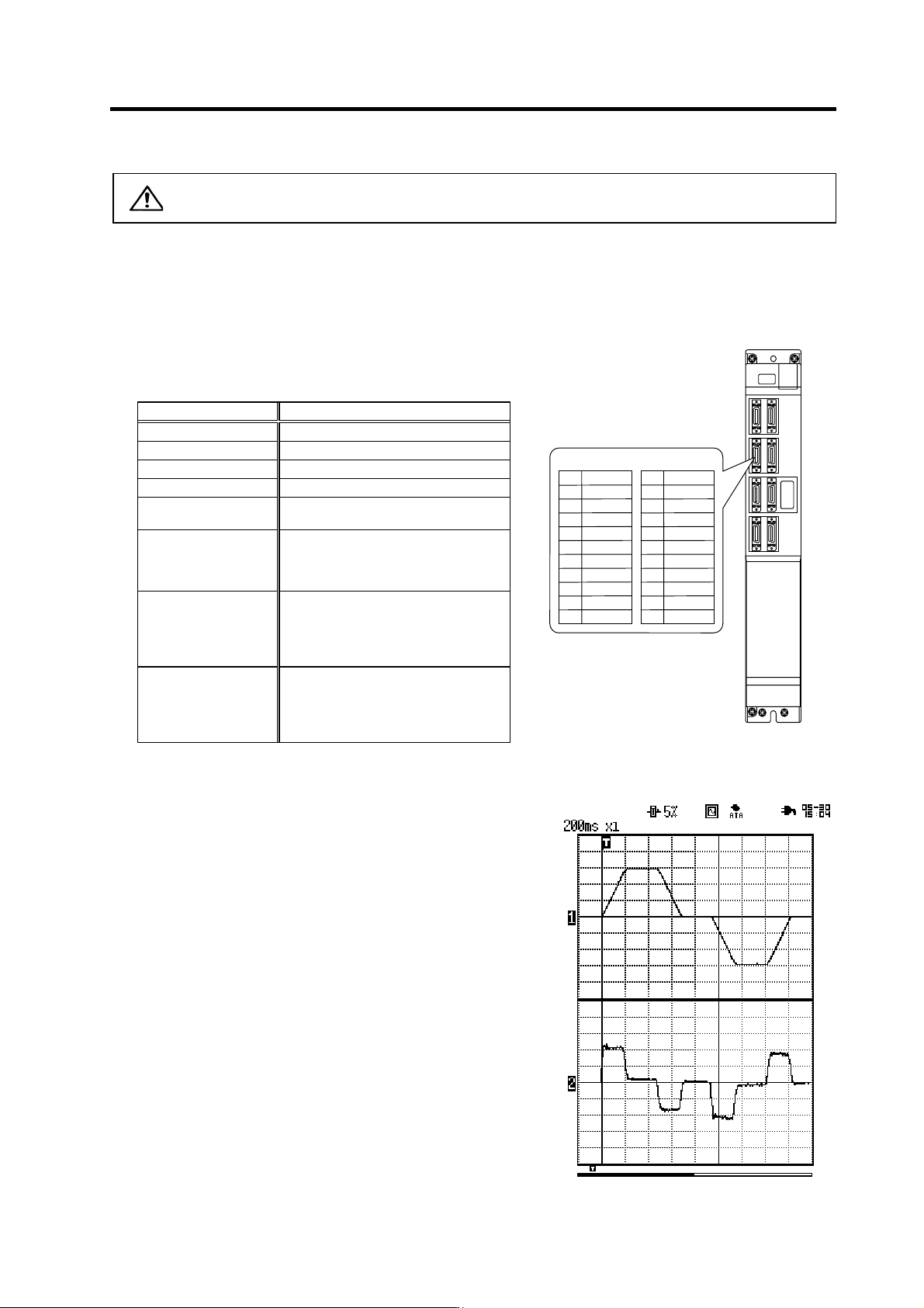
The MDS-C1-V1/V2 servo drive unit has a function to D/A output the various control data.
The servo adjustment data required for setting the servo parameters to match the machine can be D/A
output. Measure using a hi-coder, oscilloscope, etc.
4-1-1 D/A output specifications
Item Explanation
No. of channels 2ch
Output cycle 888µs (min. value)
Output precision 8bit
Output voltage range 0V to 2.5V (zero) to +5V
Output magnification
setting
±1/256 to ±128-fold
Output pin
CN9 connector
MO1 = Pin 9
MO2 = Pin 19
GND = Pins 1, 11
Function
Phase current feedback output function
L axis U phase current FB : Pin 7
L axis V phase current FB : Pin 17
M axis U phase current FB : Pin 6
M axis V phase current FB : Pin 16
Others
The D/A output for the 2-axis unit
(MDS-C1-V2) is also 2ch. When using
the 2-axis unit, set -1 for the output
data (SV061, 62) of the axis that is not
to be measured.
With the MDS-C1-V1/V2 Series, there is a 2.5V offset voltage (2.5V when data is 0), so the zero level
position must be adjusted on the hi-corder side.
+2.5 [V]
0 [V]
Speed FB
Single
shot
Current FB
+2.5 [V]
0 [V]
+5 [V]
+5 [V]
Scroll
Memory
Example of D/A out pu t wa veform
MO19
Name
LG
LUIFB
MUIFB
2
5
1
Pin
6
4
3
10
7
8
CN9 connector
MO2 19
Name
LG
LVIFB
MVIFB
12
15
11
Pin
16
14
13
20
17
18
4. Servo Adjustment
4 - 3
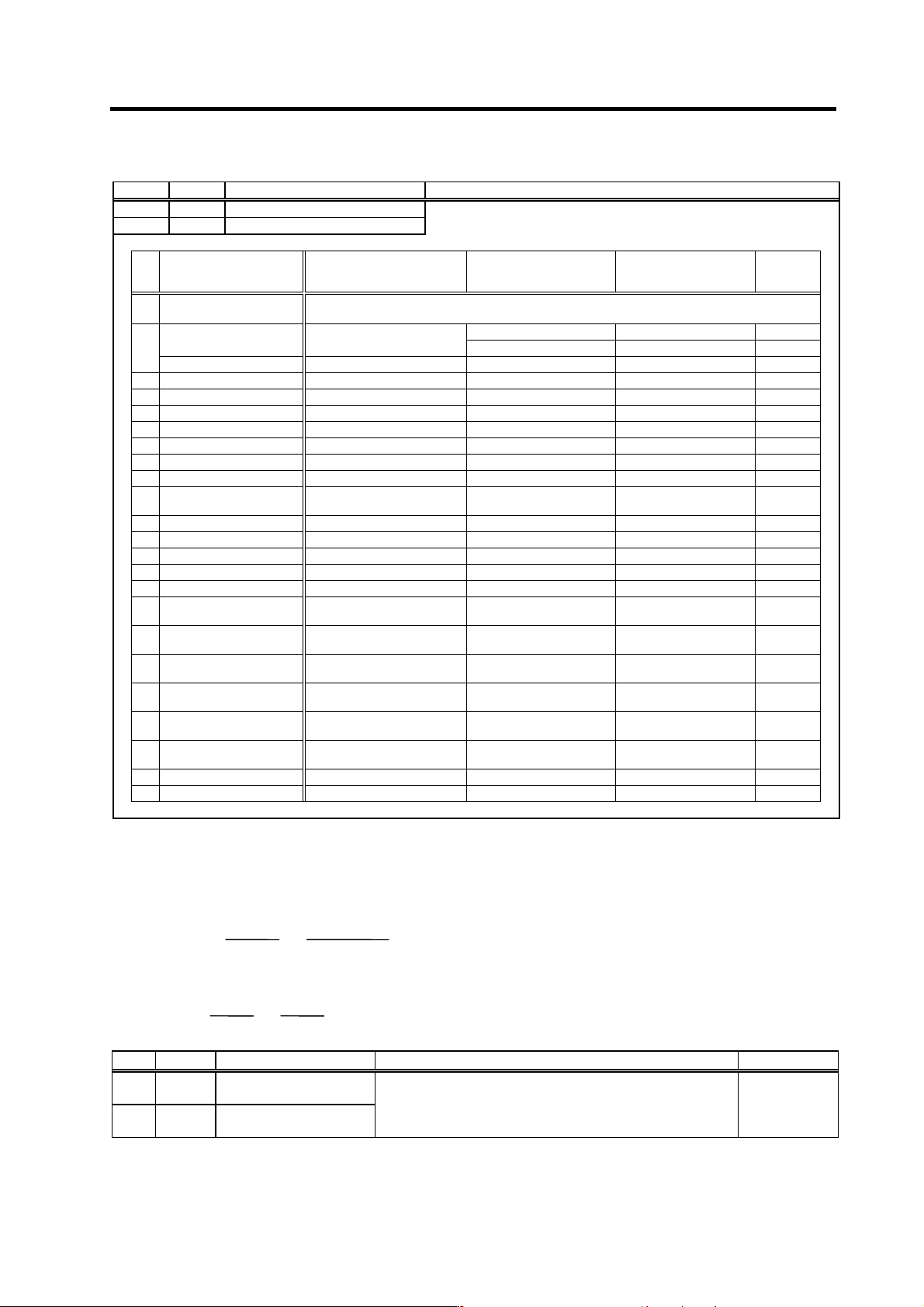
4-1-2 Output data settings
No. Abbrev. Parameter name Explanation
SV061 DA1NO D/A output channel 1 data No. Input the No. of the data to be output to each D/A output channel.
SV062 DA2NO D/A output channel 2 data No.
No. Output data Original data unit
Output magnification
standard setting value
(SV063, SV064)
Output unit for standard
setting
Output
cycle
-1 D/A output not selected
For 2-axis drive unit (MDS-C1-V2). Set the parameters to another axis in the drive unit that is not D/A
output.
13 (2000r/min) 1000r/min/V 3.55ms
0
ch1: Speed feedback r/min
9 (3000r/min) 1500r/min/V 3.55ms
ch2: Current command Stall % 131 Stall 100%/V 3.55ms
1 Current command Stall % 131 Stall 100%/V 3.55ms
2 -
3 Current feedback Stall % 131 Stall 100%/V 3.55ms
4 -
5 -
6 Position droop NC display unit/2 328 (Display unit = 1µm) 10µm/0.5V 3.55ms
7 -
8 Feedrate (F∆T)
(NC disiplay unit/2)/
Communication cycle
55 (1µm, 3.5ms) 1000 (mm/min)/0.5V 3.55ms
9 -
10 Position command NC display unit/2 328 (Display unit = 1µm) 10µm/0.5V 3.55ms
11 -
12 Position feedback NC display unit/2 328 (Display unit = 1µm) 10µm/0.5V 3.55ms
13 -
14
Collision detection
estimated torque
Stall % 131 Stall 100%/V 3.55ms
15
Collision detection
disturbance torque
Stall % 131 Stall 100%/V 3.55ms
64
Current command
(high-speed)
Internal unit 8 (adjustments required) - 888µs
65
Current feedback
(high-speed)
Internal unit 8 (adjustments required) - 888µs
77
Estimated disturbance
torque
Internal unit 8 (adjustments required) - 888µs
125
Test output saw tooth
wave
0V to 5V 0 (256) Cycle: 227.5ms 888µs
126 Test output oblong wave 0V to 5V 0 (256) Cycle 1.7ms 888µs
127 Test output 2.5V (data 0) 2.5V 0 (256) - 888µs
4-1-3 Setting the output magnification
Normally, set the standard setting value for the output scale (SV063, SV064). When "0" is set, the
magnification will be the same as "256".
DATA ×
SV063
256
×
5 [V]
256
(
8 bit
)
+ 2.5 [V] (Offset) = Output voltage [V]
(Example) To output current FB with stall 100%/V unit (SV061=3, SV063=131)
100 ×
131
256
×
5
256
+ 2.5 = 3.499 [V]
No. Abbrev. Parameter name Explanation Setting range
SV063 DA1MPY D/A output channel 1
output scale
SV064 DA2MPY D/A output channel 2
output scale
Set the output magnification with a 1/256 unit.
When "0" is set, the magnification will be the same as "256".
-32768 to 32767
(1/256-fold)