bnp-b2365(eng)b.pdf - 第146页
3. Setup 3 - 59 Standard specifications No. Abbrev. Parameter name Explanation S etting range (Unit) F E D C B A 98765 4 3 2 10 ovsn has2 has1 bit Meaning when “0” is set Meaning when “1” is set 0 has1 Setting for normal…
3. Setup
3 - 58
Standard specifications
No. Abbrev. Parameter name Explanation
S
etting range
(Unit)
Set this if overshooting occurs during positioning. This compensates the
motor torque during positioning.
This is valid only when the overshooting compensation SV027 (SSF1.ovs)
is selected.
Type 1: When SV027 (SSF1)/bitB, A (ovs)=01
Set the compensation amount based on the motor’s stall current.
This compensates overshooting that occurs during pulse feeding.
Normally, use Type 2.
Type 2: When SV027 (SSF1)/bitB, A (ovs)=10
Set the compensation amount based on the motor’s stall current.
Increase by 1% and determine the amount that overshooting doesn’t
occur.
In Type 2, compensation during the feed forward control during circular
cutting won’t be performed.
Type 3: When SV027 (SSF1)/bitB, A (ovs)=11
Use this to perform the overshooting compensation during circular
cutting or the feed forward control. The setting method is the same in
Type 2.
SV031 OVS1
Overshooting
compensation 1
When you wish different compensation amount depending on the direction
When SV042 (OVS2) is “0”, compensate with the value of SV031
(OVS1) in both of the + and -directions.
If you wish to change the compensation amount depending on the
command direction, set this and SV042 (OVS2). (SV031: + direction,
SV042: - direction. However, the directions may be opposite
depending on other settings.)
When “-1” is set, the compensation won’t be performed in the direction of
the command.
-1 to 100
(Stall [rated]
current %)
SV032 TOF
Torque offset
Set the unbalance torque of vertical axis and inclined axis. -100 to 100
(Stall [rated]
current %)
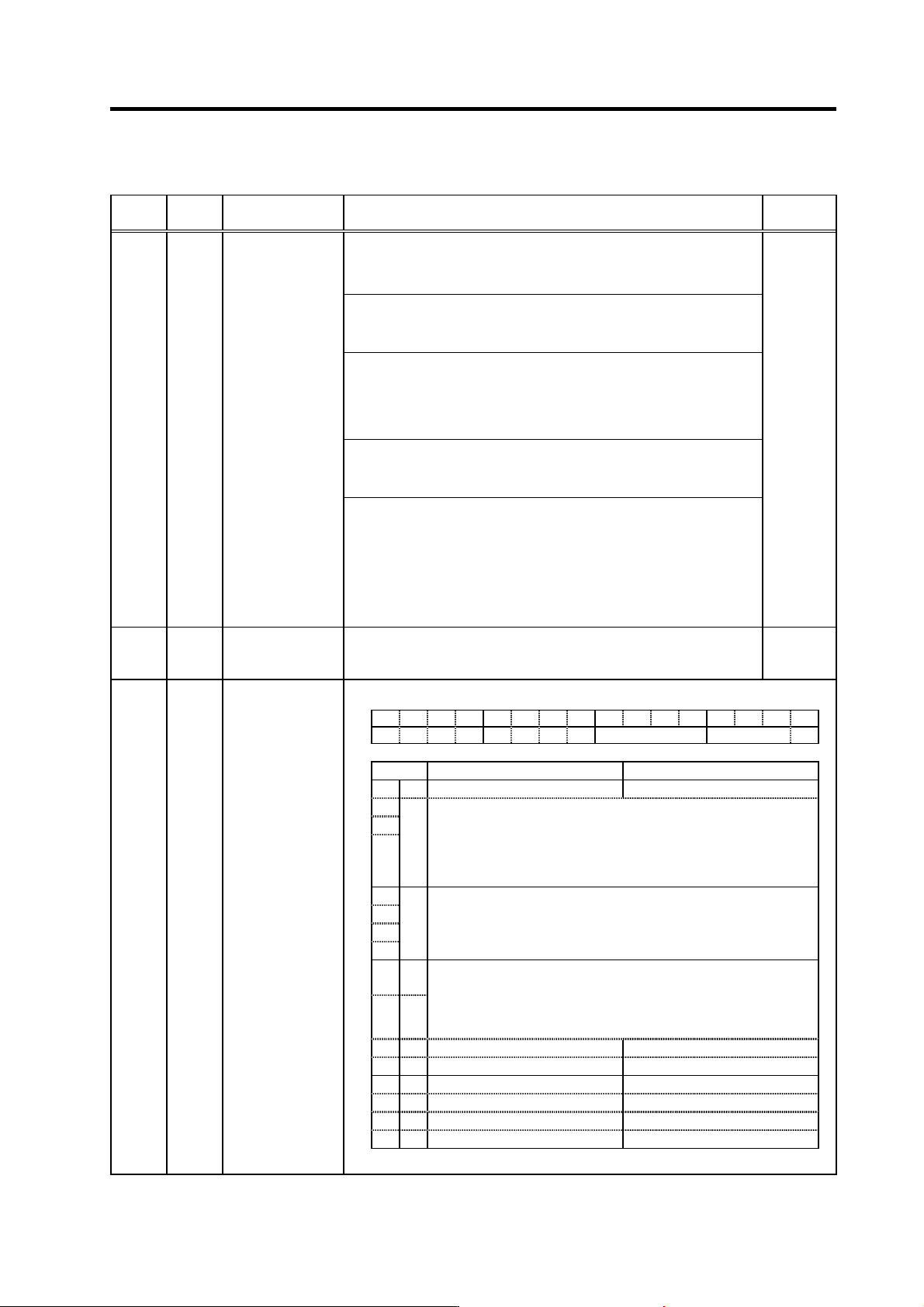
FEDCBA98765 4 3 2 10
hvx svx fhz2 nfd1 zck
bit Meaning when “0” is set Meaning when “1” is set
0 zck Z phase check valid (Alarm 42) Z phase check invalid
1 S et the filter depth for Notch filter 1 (SV038).
2 nfd1 Value 000 001 010 011 100 101 110 111
3
Depth (dB)
DeepÅ
Infntly
deep
-18.1 -12.0 -8.5 -6.0 -4.1 -2.5 -1.2
ShallowÆ
4
5
6fhz2
7
Set the operation frequency of Not ch filter 2
0: Invalid 3: 750Hz 6: 375Hz
1: 2250Hz 4: 563Hz 7: 321Hz
2 : 1125Hz 5: 450Hz 8 to F: 281Hz
8 svx
Set the performance mode of the servo control. (Only for
MDS-C1-Vx)
9hvx
00: By current loop gain
01: MDS-B-Vx compatible mode
selected
10: High gain mode selected
11: High gain mode selected
A
B
C
D
E
F
SV033 SSF2
Servo function
selection 2
(Note) Set to “0” for bits with no particular description.
Parameters with an asterisk * in the abbreviation, such as PC1*, are validated with the NC power turned ON again.
3. Setup
3 - 59
Standard specifications
No. Abbrev. Parameter name Explanation
S
etting range
(Unit)
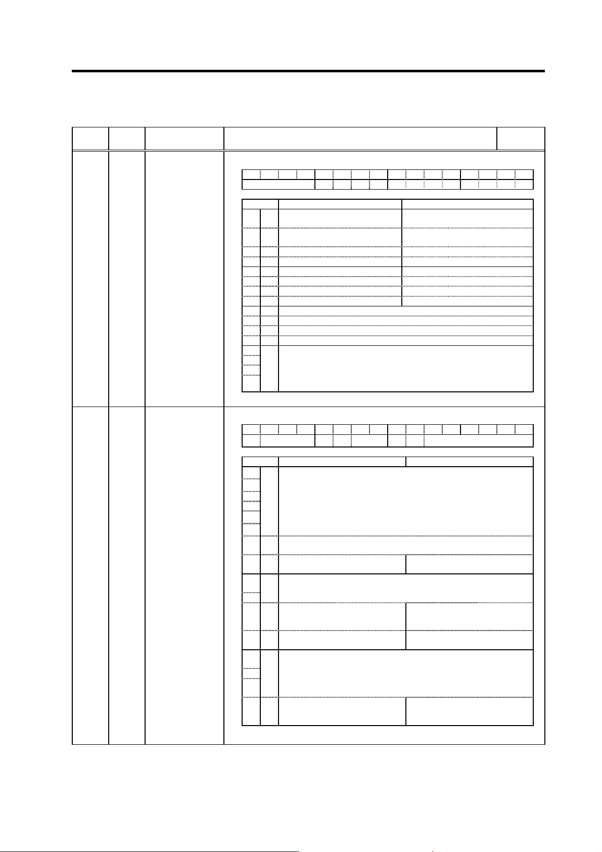
FEDCBA98765 4 3 2 10
ovsn has2 has1
bit Meaning when “0” is set Meaning when “1” is set
0 has1
Setting for normal use.
(Except for HC)
HAS control 1 valid
(HC: High acceleration rate support)
1 has2
Setting for normal use.
(Except for HC)
HAS control 2 valid
(HC: Overshooting support)
2
3
4
5
6
7
8
9
A
B
C
D
E
ovsn
F
Set the non-sensitive band of the overshooting compensation type 3 in
increments of 2m at a time.
In the feed forward control, the non-sensitive band of the model
position droop is set, and overshooting of the model is ignored. Set
2µm (0001) as a standard.
SV034 SSF3
Servo function
selection 3
(Note) Set to “0” for bits with no particular description.
HEX setting
FEDCBA98765 4 3 2 10
clt clG1 cl2n clet cltq iup tdt
bit Meaning when “0” is set Meaning when “1” is set
0
1
2
3
4
5
tdt
Td creation time setting
Set to “0”. (For machine tool builder adjustment)
6iup
Set to “1” when using any of motors from HC152 to HC702 and from
HC153 to HC453.
7 ckab
Setting for normal use No signal 2 (Alarm 21) special
detection
8
Set the retracting torque for collision detection in respect to the
maximum torque of the motor.
9
Cltq
00: 100% 01: 90% 10: 80% (Standard) 11: 70%
Aclet
Setting for normal use The disturbance torque peak of the
latest two seconds is displayed in
MPOS of the servo monitor screen.
B cl2n Collision detection method 2 valid
Collision detection method 2
invalid
C
Collision detection method 1
Set the collision detection level during cutting feed (G1).
D clG1 The G1 collision detection level=SV060*clG1.
E
When clG1=0, the collision detection method 1 during cutting feed
won’t function.
Fclt
Setting for normal use The guide value of the SV059
setting value is displayed in MPOS
of the servo monitor screen.
SV035 SSF4
Servo function
selection 4
(Note) Set to “0” for bits with no particular description.
Parameters with an asterisk * in the abbreviation, such as PC1*, are validated with the NC power turned ON again.
3. Setup
3 - 60
Standard specifications
No. Abbrev. Parameter name Explanation
Setting range
(Unit)
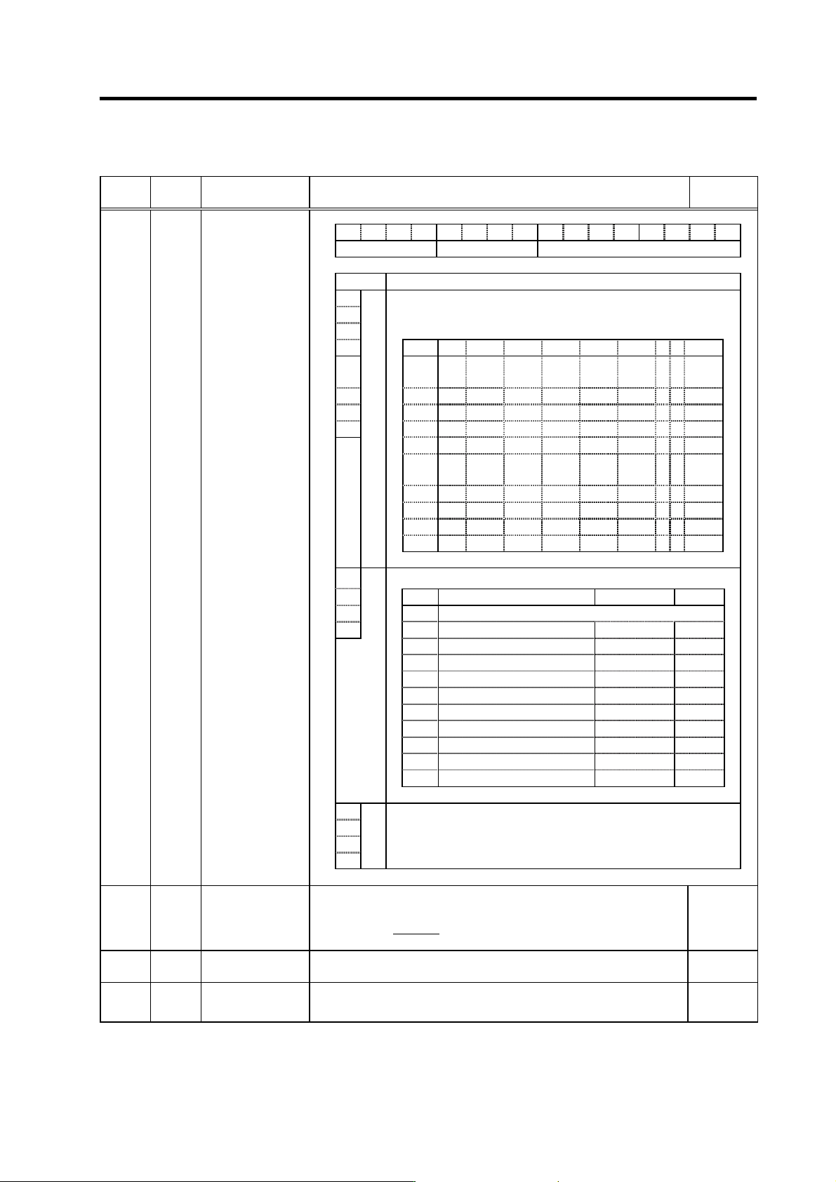
F E D C B A 9 8 7 6 5 4 3 2 1 0
amp rtyp ptyp
bit Explanation
0
1
When the CN4 connector of the drive unit and the power supply are
connected, setting below is necessary.
2 To validate the external emergency stop function, add 40h.
3 Setting 0x 1x 2x 3x 4x 5x 6x 7x 8x
4
ptyp
x0
Not
used
CV-300
5 x1 CV-110 CR-10
6 x2 CV-220 CR-15
7 x3 CR-22
x4 CV-3
7
CR-37
x5 CV-150
MDS-B-
CVE-450
MDS-B-
CVE-550
x6 CV-5
5
CV-260 CR-55
x7 CV-370
x8 CV-7
5
CR-75
x9 CV-185 CR-90
8
Set the regenerative resistor type when MDS-A-CR is used.
9
Setting Regenerative resistor model name Resistance value Capacity
A
0 MDS-C1-CV (Setting when using power supply regeneration)
B
rtyp
1 GZG200W260HMJ
26
Ω
80W
2
GZG300W130HMJ×2
26
Ω
150W
3 MR-RB30
13
Ω
300W
4 MR-RB50
13
Ω
500W
5 GZG200W200HMJ × 3
6.7
Ω
350W
6 GZG300W200HMJ × 3
6.7
Ω
500W
7 R-UNIT-1
30
Ω
700W
8 R-UNIT-2
15Ω
700W
9 R-UNIT-3
15Ω
2100W
A to F No setting
C Always set "0".
D
E
amp
F
SV036 PTYP*
Power supply type
Set “the motor inertia + motor axis conversion load inertia” in respect to the
motor inertia.
Jl+Jm Jm Motor inertia
SV037 JL
Load inertia scale
SV037(JL) =
Jm
×100
Jl Motor axis conversion load inertia
0 to 5000
(%)
SV038 FHz1
Notch filter
frequency 1
Set the vibration frequency to suppress if machine vibration occurs.
(Valid at 36 or more) When not using, set to “0”.
0 to 3000
(Hz)
SV039 LMCD
Lost motion
compensation
timing
Set this when the lost motion compensation type2 timing doest not match.
Adjust by increasing the value by 10 at a time.
0 to 2000
(ms)
Parameters with an asterisk * in the abbreviation, such as PC1*, are validated with the NC power turned ON again.