bnp-b2365(eng)b.pdf - 第210页
4. Servo Adjustment 4 - 11 4-3-2 Vibration suppression measures If vibration (machine resonance) occurs, it can be sup pressed by lowering the spee d loop gain 1 (VGN1). However, cutting precision and cycle time will be …
4. Servo Adjustment
4 - 10
(3) Adjusting the in-position width
Because there is a response delay in the servomotor drive due to position loop control, a "settling
time" is also required for the motor to actually stop after the command speed from the CNC reaches
0.
The movement command in the next block is generally started after it is confirmed that the
machine has entered the "in-position width" range set for the machine.
Set the precision required for the machine as the in-position width. If a high precision is set
needlessly, the cycle time will increase due to a delay in the settling time.
The in-position width is validated with the servo parameter settings, but there may be cases when
it is validated with the NC parameters. Refer to each NC Instruction Manual.
No. Abbrev. Parameter name Explanation Setting range
SV024 INP In-position detection
width
Set the in-position detection width.
Set the accuracy required for the machine.
The lower the setting is, the higher the positioning accuracy gets,
however, the cycle time (setting time) becomes longer. The standard
setting is "50".
0 to 32767
(µm)
POINT
The in-position width setting and confirmation availability depend on the CNC
parameters.
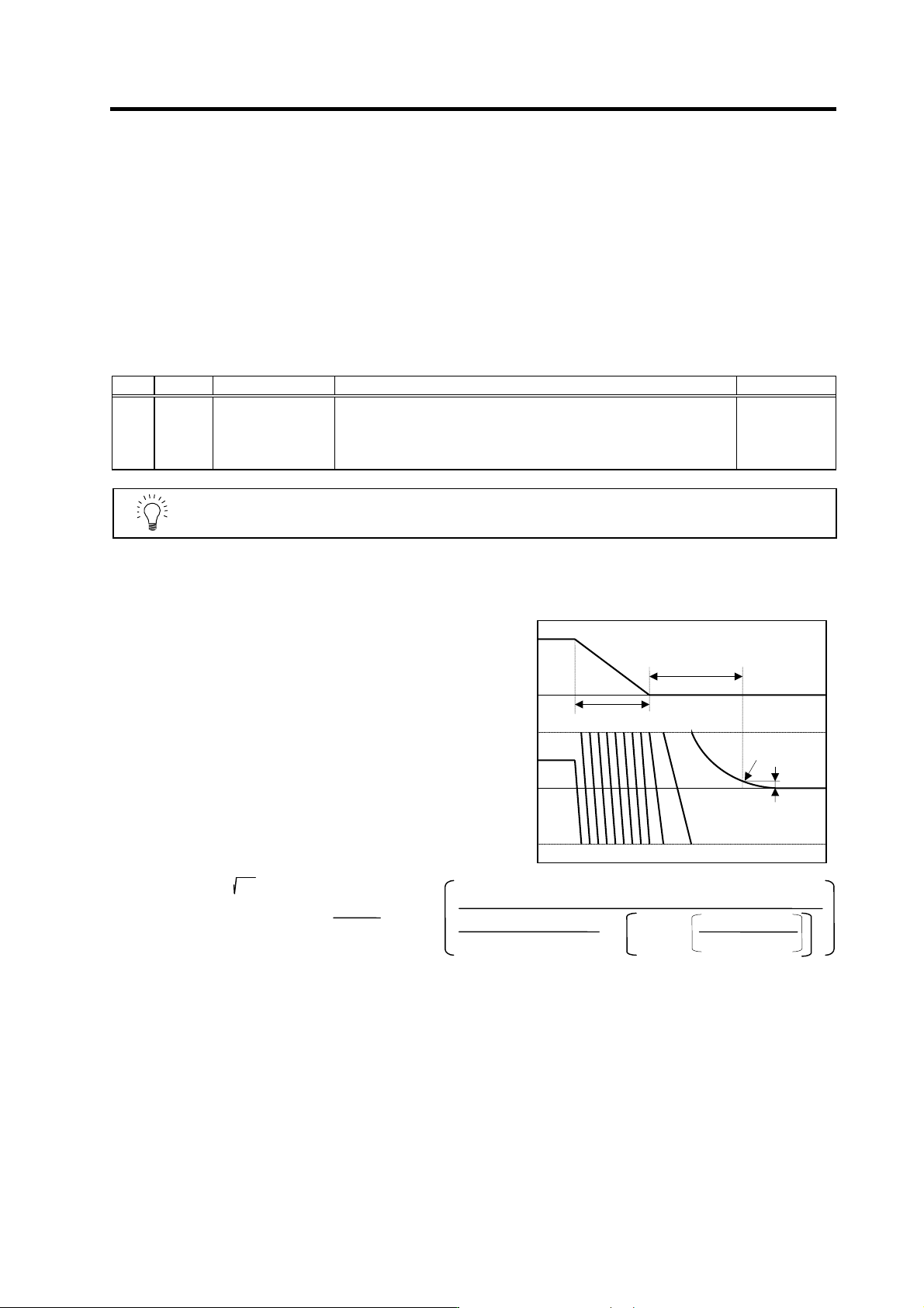
(4) Adjusting the settling tim e
The settling time is the time required for
the position droop to enter the in-position
width after the feed command (F∆T) from
the CNC reaches 0.
The settling time can be shortened by
raising the position loop gain or using
SHG control. However, a sufficient
response (sufficiently large VGN1 setting)
for the speed loop is required to carry out
stable control.
The settling time during normal control
when the CNC is set to linear acceleration/
deceleration can be calculated using the
following equation. During SHG control,
estimate the settling time by multiplying
PGN1 by
2
.
PGN1 : Position loop gain1 (SV003) (rad/s)
F : Rapid traverse rate (mm/min)
G0tL : Rapid traverse linear acceleration/
deceleration time constant (ms)
INP : In-position width (SV024) (µm)
Settling time (ms) = -
•
PGN1
10
3
INP
F × 10
6
60×G0tL×PGN1
2
×
1- exp
PGN1×G0tL
10
3
ln
0
0
F∆T
Position
droop
F
Time
Setting time
In-position
In-position width
G0tL
4. Servo Adjustment
4 - 11
4-3-2 Vibration suppression measures
If vibration (machine resonance) occurs, it can be suppressed by lowering the speed loop gain 1
(VGN1). However, cutting precision and cycle time will be sacrificed. (Refer to "4-2-2 Speed loop
gain".) Thus, try to maintain the VGN1 as high as possible, and suppress the vibration using the
vibration suppression functions.
If the VGN1 is lowered and adjusted because vibration cannot be sufficiently suppressed with the
vibration suppression functions, adjust the entire gain (including the position loop gain) again.
<Examples of vibration occurrence>
• A fine vibration is felt when the machine is touched, or a groaning sound is heard.
• Vibration or noise occurs during rapid traverse.
POINT
Suppress the vibration using the vibration suppression functions, and maintain
the speed loop gain (SV005: VGN1) as high as possible.
4. Servo Adjustment
4 - 12
(1) Notch filter
This servo drive unit mounts 5 notch filters. Measure the resonance frequency with the current
feedback analog output function, and set that frequency in parameter.
However, if the notch filter is set to a particularly low frequency, another resonance frequency that
did not vibrate initially may occur. If the notch filter's depth compensation (SV033, nfd1, nfd2) is
adjusted so that the filter does not operate unless necessary, the servo control will be stabilized.
Notch filter 3 is a filter with frequency fixed to 1125Hz, and has no depth compensation.
<Setting method>
[1] Set the resonance frequency in the notch filter frequency (1, 2, 4, 5).
[2] If the machine starts to vibrate at another frequency, raise (make shallower) the notch filter
depth compensation value, and adjust to the optimum value at which the resonance can be
eliminated.
[3] When the vibration cannot be completely eliminated, use also another notch filter for this
frequency.
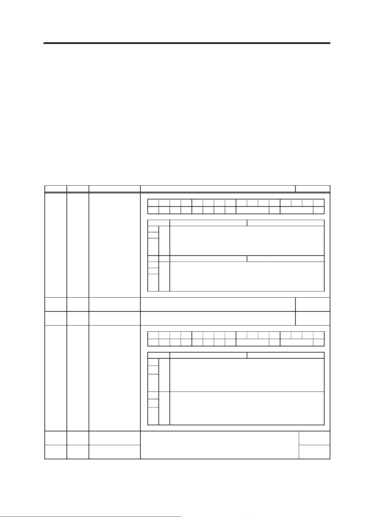
No. Abbrev. Parameter name Explanation Setting range
FEDCBA98765 4 3 2 10
hvx svx nfd2 nf3 nfd1 zck
bit Meaning when "0" is set Meaning when "1" is set
1 Set the filter depth for Notch filter 1 (SV038).
2 nfd1 Value 000 001 010 011 100 101 110 111
3
Depth (dB)
DeepÅ
Infntly
deep
-18.1 -12.0 -8.5 -6.0 -4.1 -2.5 -1.2
ShallowÆ
4 nf3 Notch filter 3 stop Notch filter 3 start (1125Hz)
5 Set the filter depth of Notch filter 2 (SV046).
6 nfd2 Value 000 001 010 011 100 101 110 111
SV033 SSF2
Servo function
selection 2
7
Depth (dB)
DeepÅ
Infntly
deep
-18.1 -12.0 -8.5 -6.0 -4.1 -2.5 -1.2
ShallowÆ
SV038 FHz1
Notch filter frequency
1
Set the vibration frequency to suppress if machine vibration occurs.
(Valid at 36 or more) When not using, set to "0".
0 to 9000
(Hz)
SV046 FHz2
Notch filter frequency
2
Set the vibration frequency to suppress if machine vibration occurs.
(Valid at 36 or more) When not using, set to "0".
0 to 9000
(Hz)
FEDCBA98765 4 3 2 10
hvx svx nfd2 nf3 nfd1 zck
bit Meaning when "0" is set Meaning when "1" is set
1 Set the filter depth for Notch filter 4 (SV038).
2 nfd4 Value 000 001 010 011 100 101 110 111
3
Depth (dB)
DeepÅ
-
∞
-18.1 -12.0 -8.5 -6.0 -4.1 -2.5 -1.2
ShallowÆ
5 Set the filter depth for Notch filter 5 (SV046).
6 nfd5 Value 000 001 010 011 100 101 110 111
SV083 SSF6
Servo function
selection 6
7
Depth (dB)
DeepÅ
-∞
-18.1 -12.0 -8.5 -6.0 -4.1 -2.5 -1.2
ShallowÆ
SV087 FHz4
Notch filter
frequency 4
0 to 2250
(Hz)
SV088 FHz5
Notch filter
frequency 5
Set the vibration frequency to suppress if machine vibration occurs.
(Valid at 141 or more) When not using, set to "0".
To use this function, set to not "0" (normally "1") when turning the power
ON. This function cannot be used with adaptive filter.
0 to 2250
(Hz)