bnp-b2365(eng)b.pdf - 第253页
5. Spindle Adjustment 5 - 8 (2) Spindle control input 2 Name Details F E D C B A 9 8 7 6 5 4 3 2 1 0 D A R P A R bit Details 0 1 2 3 4 5 6 7 8 9 A B C PAR PS alarm history clear D E DAR Alarm history clear F Spindle cont…
5. Spindle Adjustment
5 - 7
bit8. Torque limit 1 (TL1)
bit9. Torque limit 2 (TL2)
bitA. Torque limit 3 (TL3)
This signal is used to temp orarily reduce the spindle motor's output torque such as when clamping
the spindle motor on the machine side. The torque limit is designated in percentage using the
motor's short-time rating as 100%.
Set the SP021, SP049 to SP054 torque limit value with a combination of TL1 to 3.
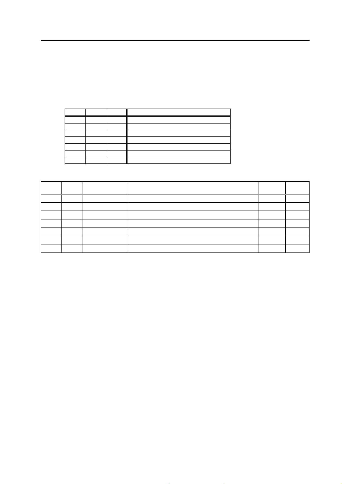
TL3 TL2 TL1 Torque limit value
0 0 1 SP021
0 1 0 SP049
0 1 1 SP050
1 0 0 SP051
1 0 1 SP052
1 1 0 SP053
1 1 1 SP054
Related spindle parameters
No. Abbr. Parameter name Details
Setting
range
Standard
SP021 TLM1 Torque limit 1 Set the torque limit rate for the torque limit signal 001. 0 to 120(%) 10
SP049 TLM2 Torque limit 2 Set the torque limit rate for the torque limit signal 010. 0 to 120(%) 20
SP050 TLM3 Torque limit 3 Set the torque limit rate for the torque limit signal 011. 0 to 120(%) 30
SP051 TLM4 Torque limit 4 Set the torque limit rate for the torque limit signal 100. 0 to 120(%) 40
SP052 TLM5 Torque limit 5 Set the torque limit rate for the torque limit signal 101. 0 to 120(%) 50
SP053 TLM6 Torque limit 6 Set the torque limit rate for the torque limit signal 110. 0 to 120(%) 60
SP054 TLM7 Torque limit 7 Set the torque limit rate for the torque limit signal 111. 0 to 120(%) 70
bitB. Pole position check command (MAC) (only for MDS-C1-SPM)
When requesting pole position che ck from NC, pole position check is performed by turning ON this
signal. However, the pole position check is not performed when the check has already completed
(control output 1/bitB=1). When SP207≠0 is set, it stars automatically on the spindle drive unit side.
bitF. Cutting (G1)
This signal is used to determine whether cutting is taking place or not during C-axis cont rol.
5. Spindle Adjustment
5 - 8
(2) Spindle control input 2
Name Details
F E D C B A 9 8 7 6 5 4 3 2 1 0
DAR PAR
bit Details
0
1
2
3
4
5
6
7
8
9
A
B
C
PAR
PS alarm history clear
D
E
DAR
Alarm history clear
F
Spindle control input 2
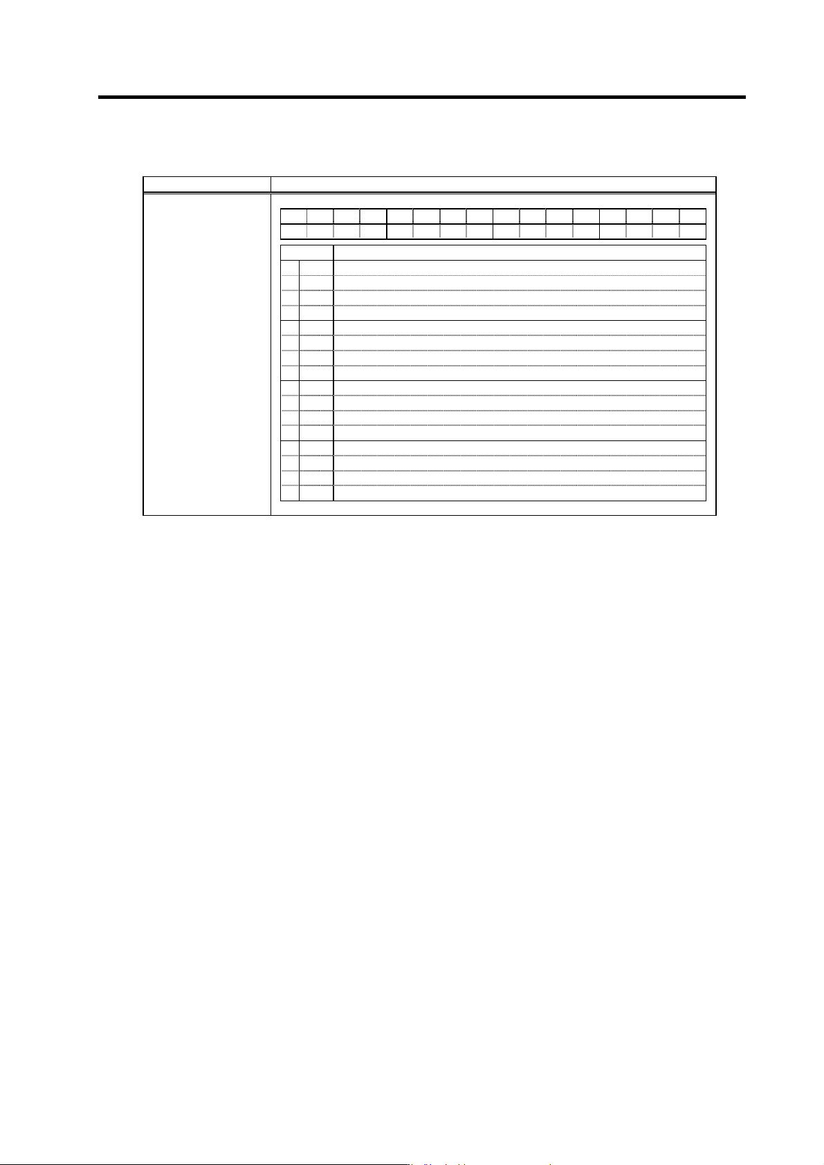
bitC. PS alarm history clear(PAR)
This signal turns ON when clearing alarm history for power supply.
bitE. Alarm history delete(DAR)
This signal turns ON when clearing alarm history for driver.
5. Spindle Adjustment
5 - 9
(3) Spindle control input 3
Name Details
F E D C B A 9 8 7 6 5 4 3 2 1 0
PCHG
MS LCS ORC WRI WRN SRI SRN GR2 GR1 SC5 SC4 SC3 SC2 SC1
bit Details
0
SC1
Spindle control mode selection command 1
1
SC2
Spindle control mode selection command 2
2
SC3
Spindle control mode selection command 3
3
SC4
Spindle control mode selection command 4
4
SC5
Spindle control mode selection command 5
5
GR1
Gear selection command 1
6
GR2
Gear selection command 2
7
8
SRN
Forward run start command
9
SRI
Reverse run start command
A
WRN
Indexing forward run command
B
WRI
Indexing reverse run command
C
ORC
Orientation start command
D
LCS
L coil selection command (When using coil changeover motor)
MS
<<For MDS-C1-SP>>
Sub-motor selection command (for 1-drive unit 2-motor changeover)
E
MCS
<<For MDS-C1-SPM>>
M coil selection command (when using coil changeover motor)
F
PCHG
Position changeover mode selection
Spindle control input 3
bit0. Spindle control mode selection command 1 (SC1)
bit1. Spindle control mode selection command 2 (SC2)
bit2. Spindle control mode selection command 3 (SC3)
bit3. Spindle control mode selection command 4 (SC4)
bit4. Spindle control mode selection command 5 (SC5)
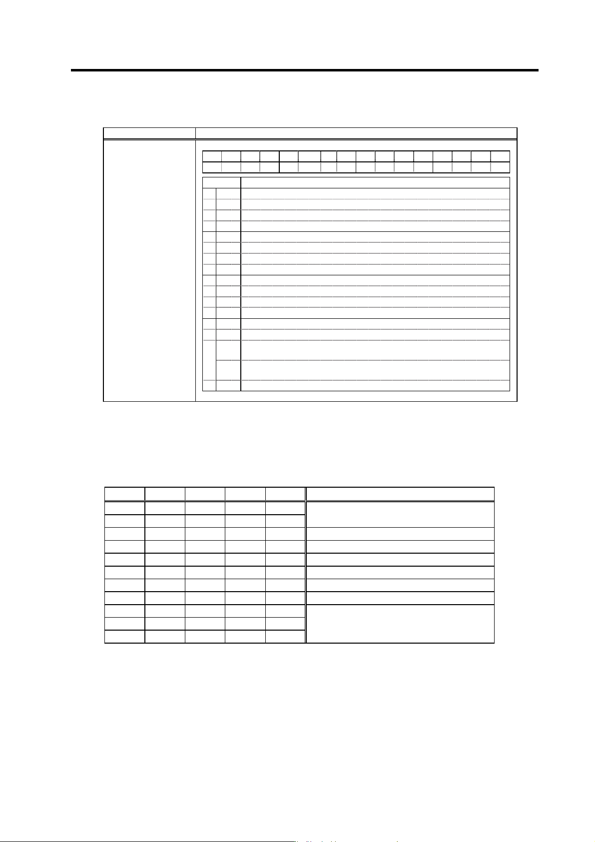
SC5 SC4 SC3 SC2 SC1 Control mode
0 0 0 * *
0 0 1 * *
Speed control
0 1 0 * * Synchronous tap control
0 1 1 0 0 C-axis control, No. 1 gain selection
0 1 1 0 1 C-axis control, No. 2 gain selection
0 1 1 1 0 C-axis control, No. 3 gain selection
0 1 1 1 1 Setting prohibited
1 0 0 * * Spindle synchronous control
1 0 1 * *
1 1 0 * *
1 1 1 * *
Setting prohibited
(Note) The asterisk indicates 1 or 0.