bnp-b2365(eng)b.pdf - 第206页
4. Servo Adjustment 4 - 7 (2) Setting the position loop gain for spindle synchronous con trol During spindle synchronous control (synchrono us t apping control, etc.), t here are three sets of position loop gain paramete…
4. Servo Adjustment
4 - 6
If there are no vibration or overshooting problems, the high-speed contour cutting precision can be
further improved by setting the VIA higher than the standard value. In this case, adjust by raising
the VIA in increments of 100 from the standard value.
Setting a higher VIA improves the trackability regarding position commands in machines for which
cycle time is important, and the time to when the position droop converges on the in-position width
is shortened.
It is easier to adjust the VIA to improve precision and cycle time if a large value (a value near the
standard value) can be set in VGN1, or if VGN1 can be raised equivalently using the disturbance
observer.
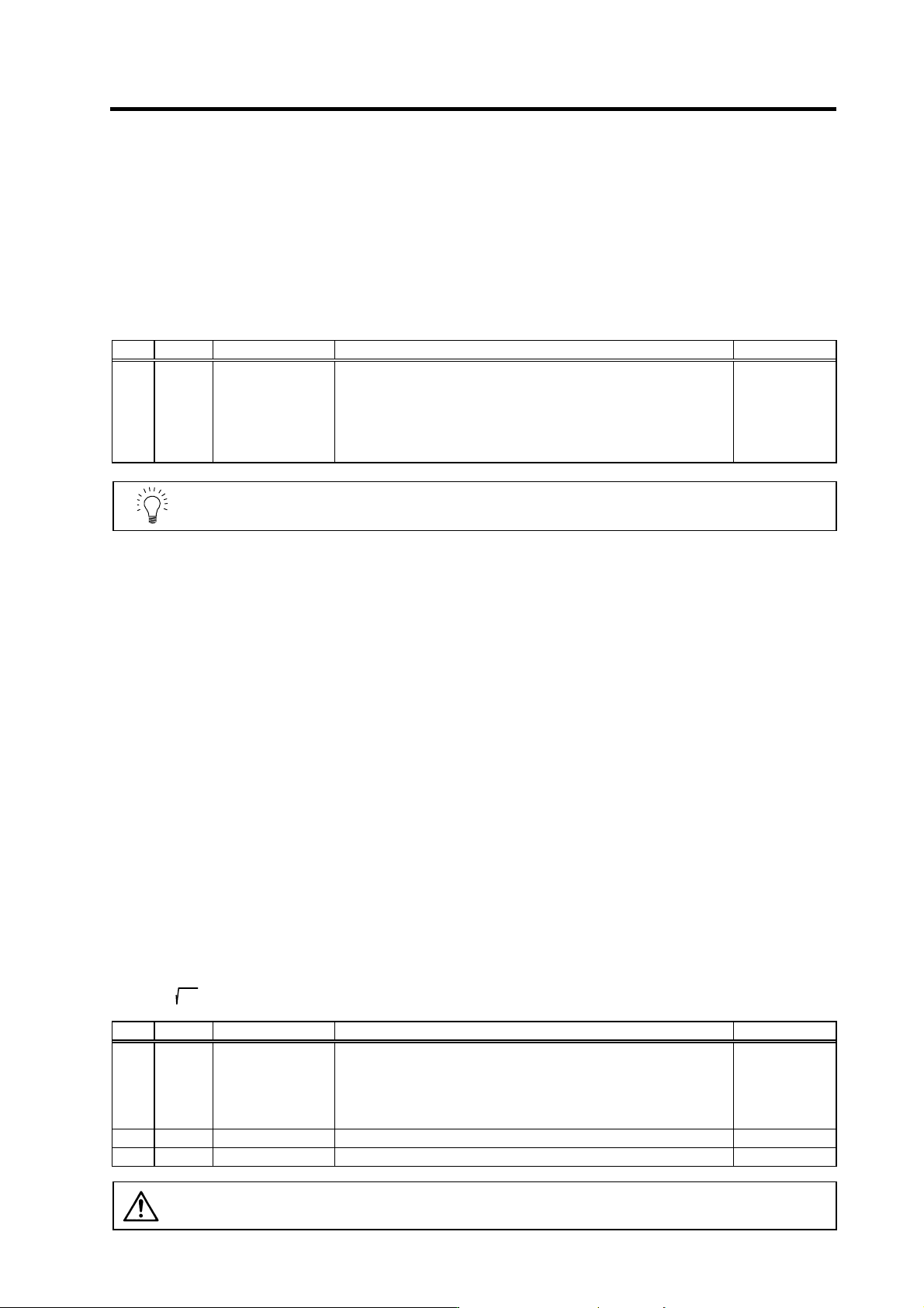
No. Abbrev. Parameter name Explanation Setting range
SV008 VIA Speed loop lead
compensation
Set the gain of the speed loop integration control.
The standard setting is "1364". During the SHG control, the standard
setting is "1900". Adjust the value by increasing/decreasing it by about
100 at a time.
Raise this value to improve contour tracking precision in high-speed
cutting. Lower this value when the position droop vibrates (10 to
20Hz).
1 to 9999
POINT
Position droop vibration of 10Hz or less is not leading compensation control
vibration. The position loop gain must be adjusted.
4-2-3 Position loop gain
(1) Setting the position loop gain
The position loop gain 1 (SV003: PGN1) is a parameter that determines the trackability to the
command position. 47 is set as a standard. Set the same position loop gain value between
interpolation axes.
When PGN1 is raised, the trackability will be raised and the settling time will be shortened, but a
speed loop that has a responsiveness that can track the position loop gain with increased
response will be required. If the speed loop responsiveness is insufficient, several Hz of vibration
or overshooting will occur during acceleration/deceleration. Vibration or overshooting will also
occur when VGN1 is smaller than the standard value during VIA adjustment, but the vibration in
the position loop occurs generally 10Hz or less. (The VIA vibration occurs from 10 to 20Hz.) When
the position control includes machine resonance points (Position control machine resonance
points occur at the tool end parts, etc.) because of insufficient machine rigidity, the machine will
vibrate during positioning, etc. In either case, lower PGN1 and adjust so that vibration does not
occur.
If the machine also vibrates due to machine backlash when the motor stops, the vibration can be
suppressed by lowering the PGN1 and smoothly stopping.
If SHG control is used, an equivalently high position loop gain can be maintained while
suppressing these vibrations. To adjust the SHG control, gradually raise the gain from a setting
where 1/2 of a normal control PGN1 where vibration did not occur was set in PGN1. If the PGN1
setting value is more than 1/2 of the normal control PGN1 when SHG control is used, there is an
improvement effect in position control. (Note that for the settling time the improvement effect is at
1/
2
or more.)
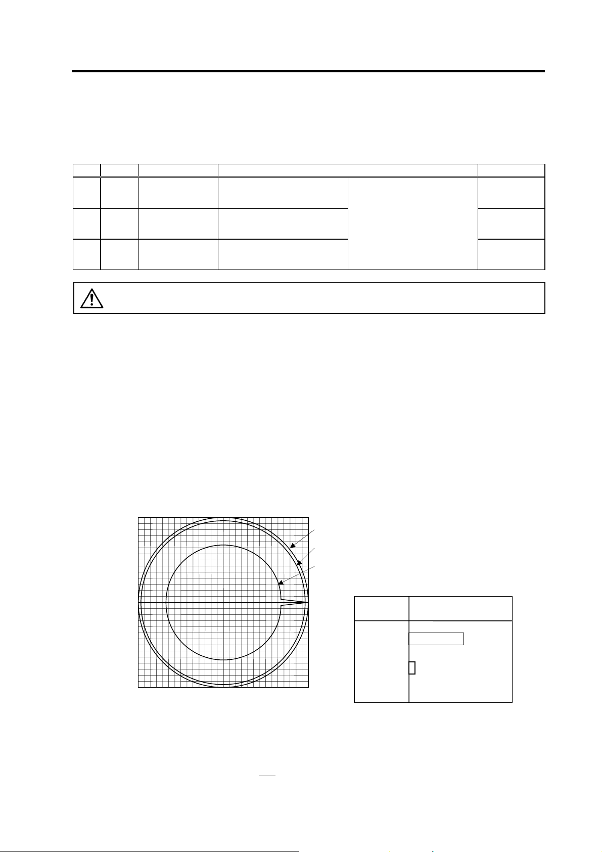
No. Abbrev. Parameter name Explanation Setting range
SV003 PGN1 Position loop gain 1
Set the position loop gain. The standard setting is "47".
The higher the setting value is, the more precisely the command can be
followed and the shorter the positioning time gets, however, note that a
bigger shock is applied to the machine during acceleration/deceleration.
When using the SHG control, also set SV004 (PGN2) and SV057
(SHGC).
1 to 200
(rad/s)
SV004 PGN2 Position loop gain 2 Set 0. (For SHG control) 0 to 999
SV057 SHGC SHG control gain Set 0. (For SHG control) 0 to 1200
CAUTION
Always set the same value for the position loop gain between the interpolation
axes.
4. Servo Adjustment
4 - 7
(2) Setting the position loop gain for spindle synchronous con trol
During spindle synchronous control (synchronous tapping control, etc.), there are three sets of
position loop gain parameters besides the normal control.
No. Abbrev. Parameter name Explanation Setting range
SV049 PGN1sp Position loop gain 1
in spindle
synchronous control
Set 15 as a standard. 1 to 200
(rad/s)
SV050 PGN2sp Position loop gain 2
in spindle
synchronous control
Set 0 as a standard.
(For SHG control)
0 to 999
SV058 SHGCsp SHG control gain in
spindle synchronous
control
Set 0 as a standard.
(For SHG control)
Set the same parameter as the
position loop gain for the spindle
synchronous control.
0 to 1200
CAUTION
Always set the same value for the position loop gain between the spindle and
servo synchronous axes.
(3) SHG control (option function)
If the position loop gain is increased or feed forward control (NC function) is used to shorten the
settling time or increase the precision, the machine system may vibrate easily.
SHG control changes the position loop to a high-gain by stably compensating the servo system
position loop through a delay. This allows the settling time to be reduced and a high precision to be
achieved. (SHG: Smooth High-Gain)
(Feature 1) When the SHG control is set, even if PGN1 is set to the same value as the
conventional gain, the position loop gain will be doubled.
(Feature 2) The SHG control response is smoother than conventional position control during
acceleration/deceleration, so the gain can be increased further with SHG control
compared to the conventional position control.
(Feature 3) With SHG control, a high gain is achieved so a high precision can be obtained during
contour control.
The following drawing shows an example of the improvement in roundness
characteristics with SHG control.
Shape error characteristics
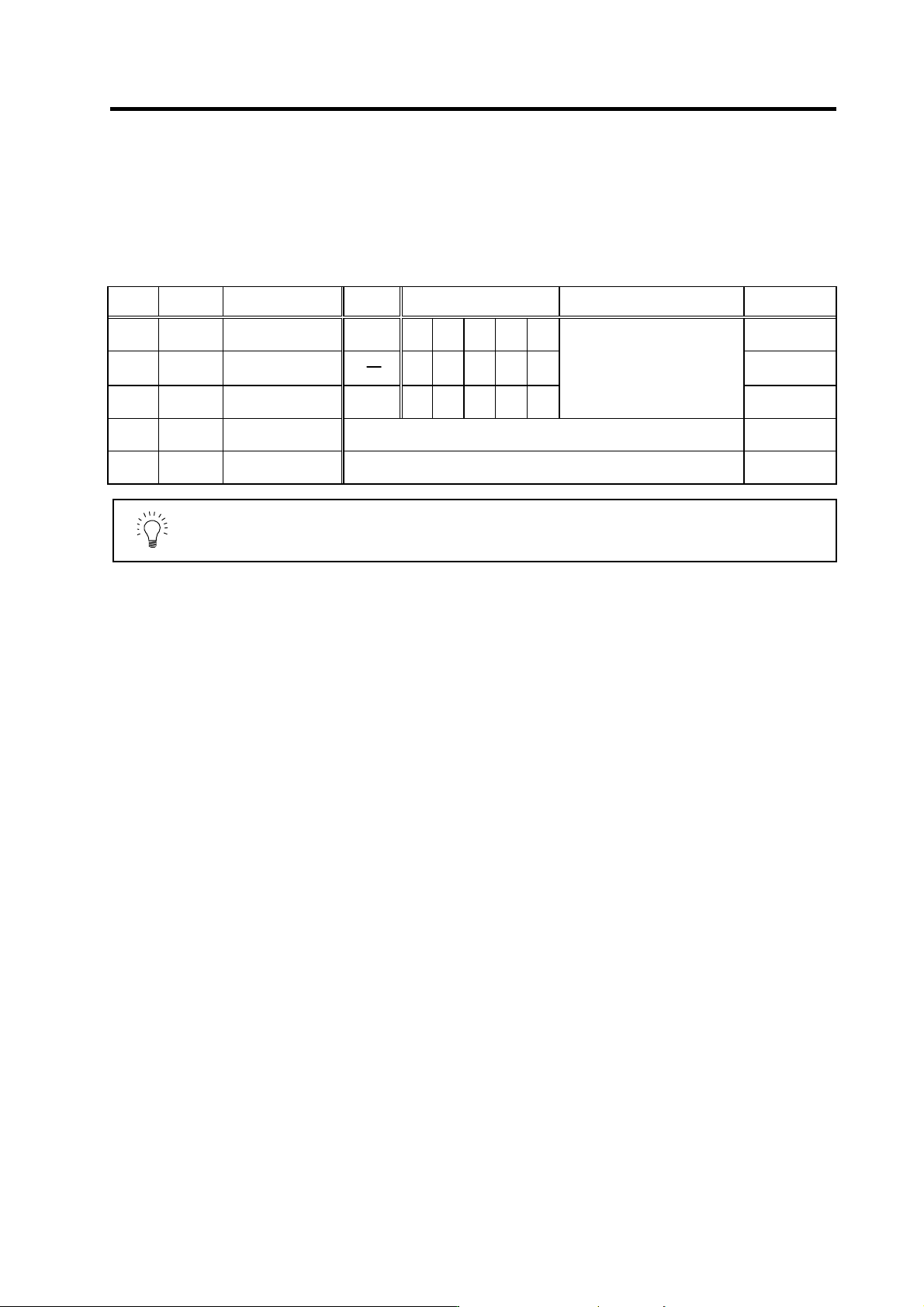
During SHG control, PGN1, PGN2 and SHGC are set with the following ratio.
PGN1 : PGN2 : SHGC = 1 :
8
3
: 6
(F=3000mm/min, ERROR=5.0µm/div)
-50.0 50.00.0
0.0
-50.0
50.0
[1] : Commanded path
[2] : SHG control (PGN1=47)
[3] : Conventional control (PGN1=33)
Conventional
control
SHG control
Control
method
Roundness error (
µ
m)
2.5
22.5
<Effect>
4. Servo Adjustment
4 - 8
During SHG control even if the PGN1 setting value is the same, the actual position loop gain will be
higher, so the speed loop must have a sufficient response. If the speed loop response is low,
vibration or overshooting could occur during acceleration/deceleration in the same manner as
conventional control. If the speed loop gain has been lowered because machine resonance occurs,
lower the position loop gain and adjust.
No.
Abbrev.
Parameter name
Setting
ratio
Setting example Explanation Setting range
SV003
(SV049)
PGN1
(PGN1sp)
Position loop gain 1
1 23 26 33 38 47
1 to 200
SV004
(SV050)
PGN2
(PGN2sp)
Position loop gain 2 8
3
62 70 86 102 125
0 to 999
SV057
(SV058)
SHGC
(SHGCsp)
SHG control gain
6 140 160 187 225 281
Always set with a combination of
these three parameters.
0 to 999
SV008 VIA Speed loop lead
compensation
Set 1900 as a standard for SHG control. 1 to 9999
SV015 FFC Acceleration rate
feed forward gain
Set 100 as a standard for SHG control. 0 to 999
POINT
The SHG control is an optional function. If the option is not set in the CNC, the
alarm 37 (at power ON) or warning E4, Error Parameter No. 104 (2304 for
M60S/E60 Series CNC) will be output.