bnp-b2365(eng)b.pdf - 第20页
1. Installation 1 - 4 1-1-5 Shaft characteristics There is a limit to the load that can be applied on the motor shaft. Make sure that the load applied on the radial direction and thrust direction, when mounted on the mac…
1. Installation
1 - 3
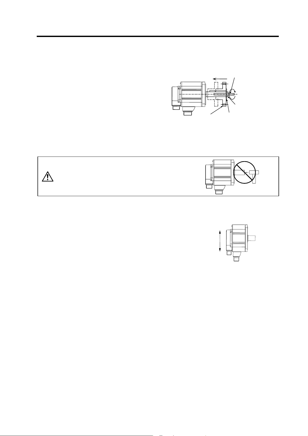
1-1-3 Cautions for mounting load (prevention of impact on shaft)
[1] When using the servomotor with key way, use
the screw hole at the end of the shaft to mount
the pulley onto the shaft. To install, first place
the double-end stud into the shaft screw
holes, contact the coupling end surface
against the washer, and press in as if
tightening with a nut. When the shaft does not
have a key way, use a frictional coupling, etc.
[2] When removing the pulley, use a pulley
remover, and make sure not to apply an
impact on the shaft.
Servomoto
r
Double-end stud
Nut
Pulle
y
Washe
r
[3] Install a protective cover on the rotary sections such as the pulley installed on the shaft to ensure
safety.
[4] The direction of the detector installed on the servomotor cannot be changed.
CAUTION
Never hammer the end of the shaft
during assembly.
1-1-4 Installation direction
[1] There are no restrictions on the installation direction. Installation
in any direction is possible, but as a standard the motor is
installed so that the motor power line and detector cable cannon
plugs (lead-in wires) face downward. Installation in the standard
direction is effective against dripping. Measure to prevent oil and
water must be taken when not installing in the standard direction.
When the motor is not installed in the standard direction, refer to
section "1-1-6 Oil/water standards" and take the appropriate
measures.
The brake plates may make a sliding sound when a servomotor
with magnetic brake is installed with the shaft facing upward, but
this is not a fault.
Up
Down
Standard installation
d
ir
ect
i
o
n
1. Installation
1 - 4
1-1-5 Shaft characteristics
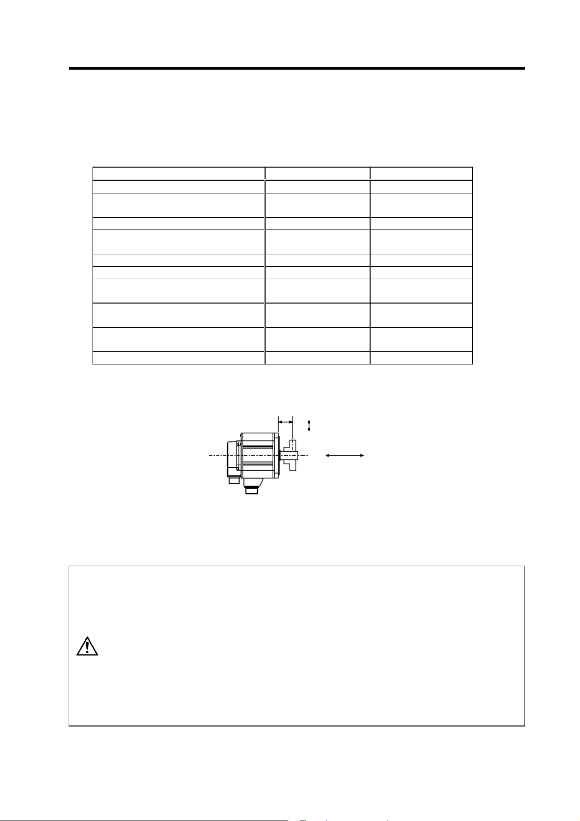
There is a limit to the load that can be applied on the motor shaft. Make sure that the load applied on the
radial direction and thrust direction, when mounted on the machine, is below the tolerable values given
below. These loads may affect the motor output torque, so consider them when designing the machine.
Servomotor Tolerable radial load Tolerable thrust load
HA053NS, HA13NS 78.4N (L=26mm) 49N
HA23NS, HA33NS
HA23NT, HA33NT
245N (L=30 mm) 147N
HC103RT, HC153RT, HC203RT 392N (L=45 mm) 196N
HC52T, HC102T, HC152T
HC53T, HC103T, HC153T
392N (L=58 mm) 490N
HC103RS, HC153RS, HC203RS 686N (L=45 mm) 196N
HC353RS, HC503RS 980N (L=63 mm) 392N
HC52S, HC102S, HC152S
HC53S, HC103S, HC153S
980N (L=55 mm) 490N
HC202S, HC352S, HC452S, HC702S
HC203S, HC353S, HC453S, HC703S
2058N (L=79 mm) 980N
HC902S
HA-LF11K2-S8
2450N (L=85 mm) 980N
HA-LF15K2-S8 2940N (L=100 mm) 980N
Note: The symbol L in the table refers to the value of L below.
Thrust load
Radial load
L
L : Length from flange installation surface to center of load weight [mm]
CAUTION
1. Use a flexible coupling when connecting with a ball screw, etc., and keep the
shaft core deviation to below the tolerable radial load of the shaft.
2. When directly installing the gear on the motor shaft, the radial load increases
as the diameter of the gear decreases. This should be carefully considered
when designing the machine.
3. When directly installing the pulley on the motor shaft, carefully consider so
that the radial load (double the tension) generated from the timing belt tension
is less than the values shown in the table above.
4. In machines where thrust loads such as a worm gear are applied, carefully
consider providing separate bearings, etc., on the machine side so that loads
exceeding the tolerable thrust loads are not applied to the motor.
5. Do not use a rigid coupling as an excessive bending load will be applied on
the shaft and could cause the shaft to break.
1. Installation
1 - 5
1-1-6 Oil/water standards
[1] The motor protective format uses the IP type, which complies with IEC
Standard. However, these Standards are short-term performance
specifications. They do not guarantee continuous environmental
protection characteristics. Measures such as covers, etc., must be
taken if there is any possibility that oil or water will fall on the motor,
and the motor will be constantly wet and permeated by water. Note
that the motor’s IP-type is not indicated as corrosion-resistant.
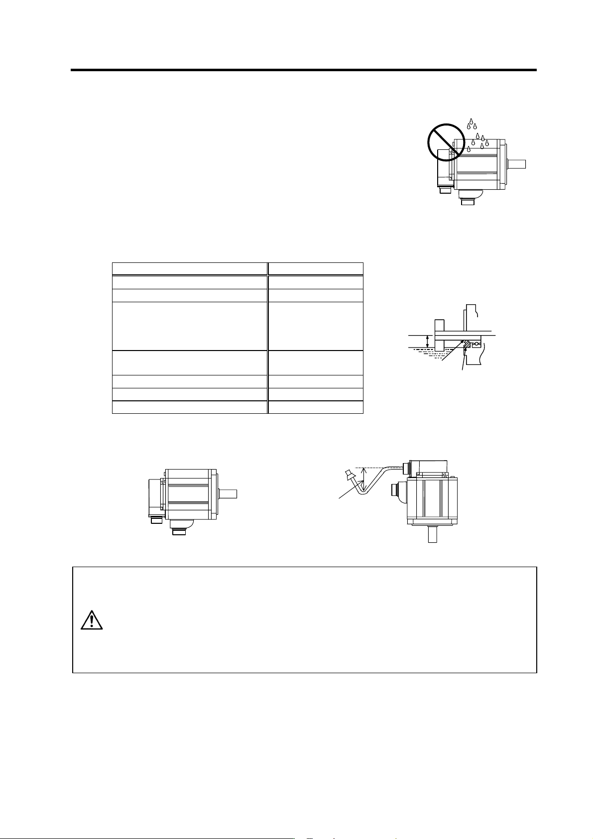
[2] When a gear box is installed on the servomotor, make sure that the oil
level height from the center of the shaft is higher than the values given below. Open a breathing
hole on the gear box so that the inner pressure does not rise.
Servomotor Oil level (mm)
HA053N, HA13N 8
HA23N, HA33N 10
HC52, HC102, HC152
HC53, HC103, HC153
HC103R, HC153R, HC203R
HC353R, HC503R
20
HC202, HC352, HC452, HC702
HC203, HC353, HC453, HC703
25
HC902 30
HA-LF11K2-S8 34
HA-LF15K2-S8 48
Oil level
Lip
V-ring
Servomoto
r
Gea
r
[3] When installing the servomotor horizontally, set the power cable and detector cable to face
downward. When installing vertically or on an inclination, provide a cable trap.
Cable trap
CAUTION
1. The servomotors, including those having IP65 specifications, do not have a
completely waterproof (oil-proof) structure. Do not allow oil or water to
constantly contact the motor, enter the motor, or accumulate on the motor. Oil
can also enter the motor through cutting chip accumulation, so be careful of
this also.
2. When the motor is installed facing upwards, take measures on the machine
side so that gear oil, etc., does not flow onto the motor shaft.
3. Do not remove the detector from the motor. (The detector installation screw is
treated for sealing.)
Oil or water
Servomotor