bnp-b2365(eng)b.pdf - 第347页
6. Troubleshooting 6 - 42 W arning No. A8 T urret indexing error warning The commanded turret indexing position shift amount is outside the specified range. Investigation det ails In vestigation results Remedies SV SP Th…
6. Troubleshooting
6 - 41
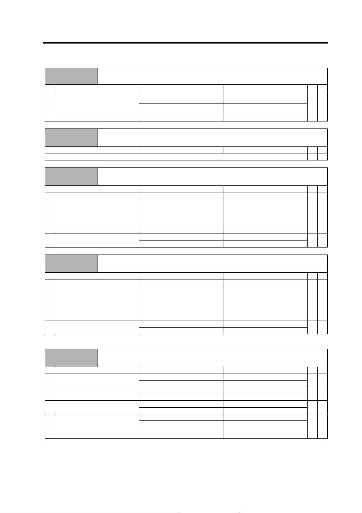
Warning No.
93
Initial absolute position fluctuation
The position data fluctuated when creating the initial absolute position.
Investigation details Investigation results Remedies SV SP
The vertical axis or slant axis drops
when the NC power is turned ON.
Check the brake operation. 1 Check the state of the axis when the
NC power is turned ON.
The axis moves with an external
force when the NC power is turned
ON.
Make sure that the axis does not
move when the power is turned ON.
{
Warning No.
96
MP scale feedback error
An excessive deviation was detected between the motor end detector and MP scale feedback data for
the MP scale absolute position detection system.
Investigation details Investigation results Remedies SV SP
1 Check the alarm No. "43" items.
{
Warning No.
97
MP scale offset error
An error was detected in the offset data received from the MP scale for the MP scale absolute position
detection system.
Investigation details Investigation results Remedies SV SP
No abnormality is found in particular. Investigate item 2. 1 Check if there is any abnormality in
the detector's ambient environment.
(Ex. Ambient temperature, noise,
grounding)
An abnormality was found in the
ambient environment.
Take remedies according to the
causes of the abnormality.
Ex. High temperature:
Check the cooling fan.
Incomplete grounding:
Additionally ground.
{
Occurs frequently. Replace the detector. 2 Check the repeatability.
Is not repeated. Investigate item 1.
{ {
Warning No.
9E
Absolute position detector, multi-rotation counter error
An error was detected in the multi-rotation counter for the absolute position detector. The absolute
position cannot be compensated.
Investigation details Investigation results Remedies SV SP
No abnormality is found in particular. Investigate item 2. 1 Check if there is any abnormality in
the detector's ambient environment.
(Ex. Ambient temperature, noise,
grounding)
An abnormality was found in the
ambient environment.
Take remedies according to the
causes of the abnormality.
Ex. High temperature:
Check the cooling fan.
Incomplete grounding:
Additionally ground.
{
Occurs frequently. Replace the detector. 2 Check the repeatability.
Is not repeated. Investigate item 1.
{ {
(Note) When this alarm occurs, the absolute position system's zero point must be established.
Warning No.
9F
Battery voltage drop
The voltage of the battery supplying to the absolute position detector has dropped. The absolute
position data is held.
Investigation details Investigation results Remedies SV SP
Less than 3V. Replace the battery unit. 1 Measure the battery (MDS-A-BT)
voltage.
3V or more. Investigate item 2.
{
The cable is disconnected. Connect correctly. 2 Check whether the NC bus cable is
disconnected.
There is no problem. Investigate item 3.
{
The cable is broken. Replace the cable. 3 Check whether the battery wire in the
detector cable is broken.
The cable is not broken. Investigate item 4.
{
Improved. Replace the drive unit. 4 Try replacing the drive unit.
Not improved. Replace the detector.
(With the absolute position system,
the zero point must be established.)
{
(Note) When warning 9F occurs, do not turn the drive unit power OFF to ensure that the absolute position data is held.
Replace the battery with the drive unit power ON.
6. Troubleshooting
6 - 42
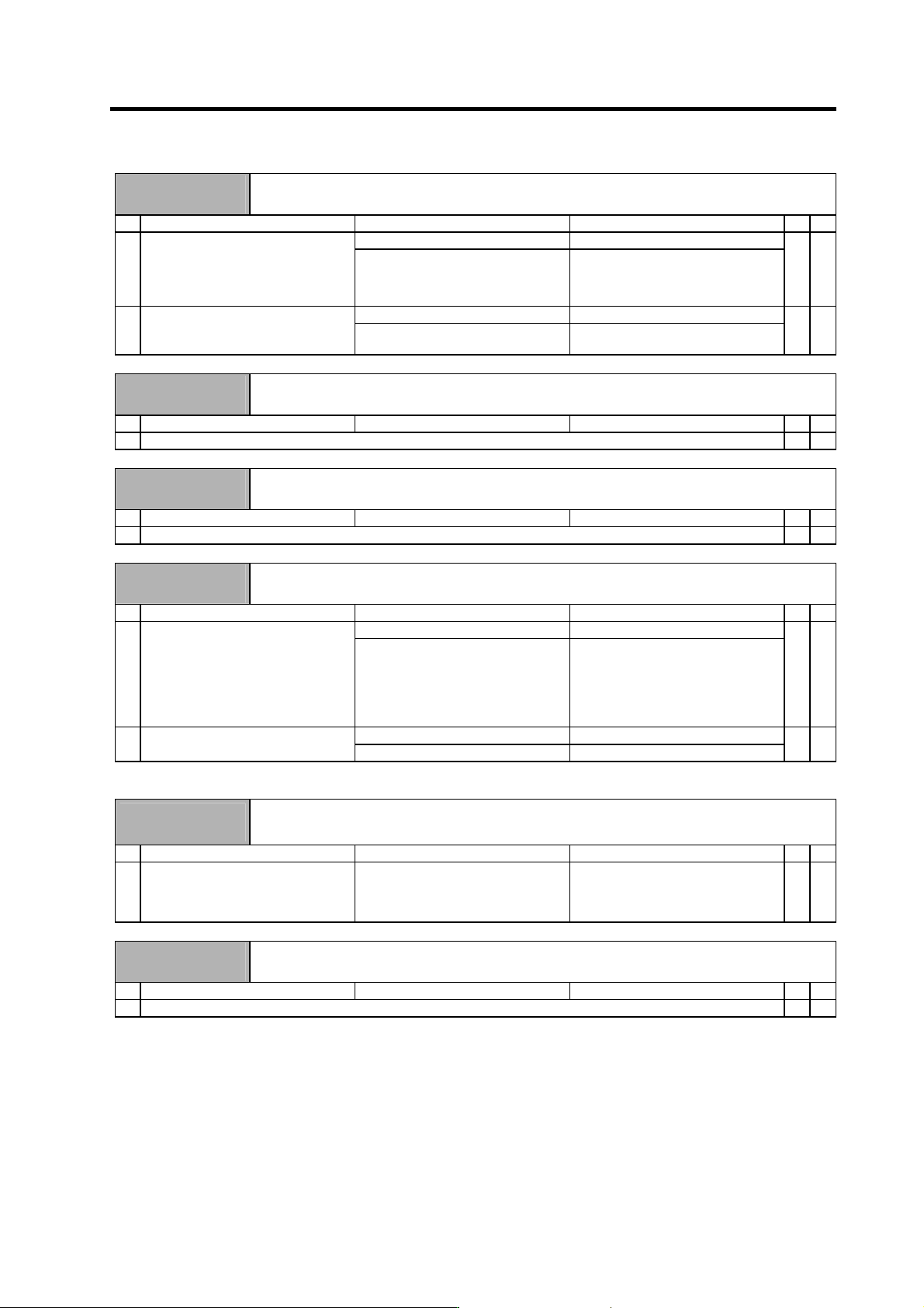
Warning No.
A8
Turret indexing error warning
The commanded turret indexing position shift amount is outside the specified range.
Investigation details Investigation results Remedies SV SP
The setting is incorrect. Correctly set SP097. 1 Check the parameters.
SP097/bitB = 0 command angle 1°
unit
SP097/bitB = 1 command angle
0.1° unit
The setting is correct. Investigate item 2.
{
The position can be pinpointed. Check the PLC program process. 2 Pinpoint where the alarm occurs in
the PLC program.
The position cannot be pinpointed. Investigate the details of the NC and
PLC program process.
{
Warning No.
A9
Orientation feedback error warning
Retrying during an orientation feedback error.
Investigation details Investigation results Remedies SV SP
1 Check the alarm No. "5C" items.
{
Warning No.
E1
Overload warning
The overload detection level is 80% or more.
Investigation details Investigation results Remedies SV SP
1 Check the alarm No. "50" items.
{ {
Warning No.
E3
Absolute position counter warning
A deviation was detected in the absolute position data and relative position data.
Investigation details Investigation results Remedies SV SP
No abnormality is found in particular. Investigate item 2. 1 Check if there is any abnormality in
the detector's ambient environment.
(Ex. Ambient temperature, noise,
grounding)
An abnormality was found in the
ambient environment.
Take remedies according to the
causes of the abnormality.
Ex. High temperature:
Check the cooling fan.
Incomplete grounding:
Additionally ground.
{
Occurs frequently. Replace the detector. 2 Check the repeatability.
Is not repeated. Investigate item 1.
{
(Note) When this alarm occurs, the absolute position system's zero point must be established.
Warning No.
E4
Parameter error warning
A parameter exceeding the setting range was set.
"S51 parameter error ####" is displayed on the NC screen. #### indicates the incorrect parameter No.
Investigation details Investigation results Remedies SV SP
1 Check the error parameter No. SV001 to SV065
(M60S system: 2201 to 2265)
SP001 to SP384
(M60S system: 3201 to 3584)
Set the value within the designated
setting range.
{ {
Warning No.
E6
Control axis removal warning
Control axis removal was commanded.
Investigation details Investigation results Remedies SV SP
1 The status in which removal of the control axis was commanded from the NC is indicated.
{
6. Troubleshooting
6 - 43
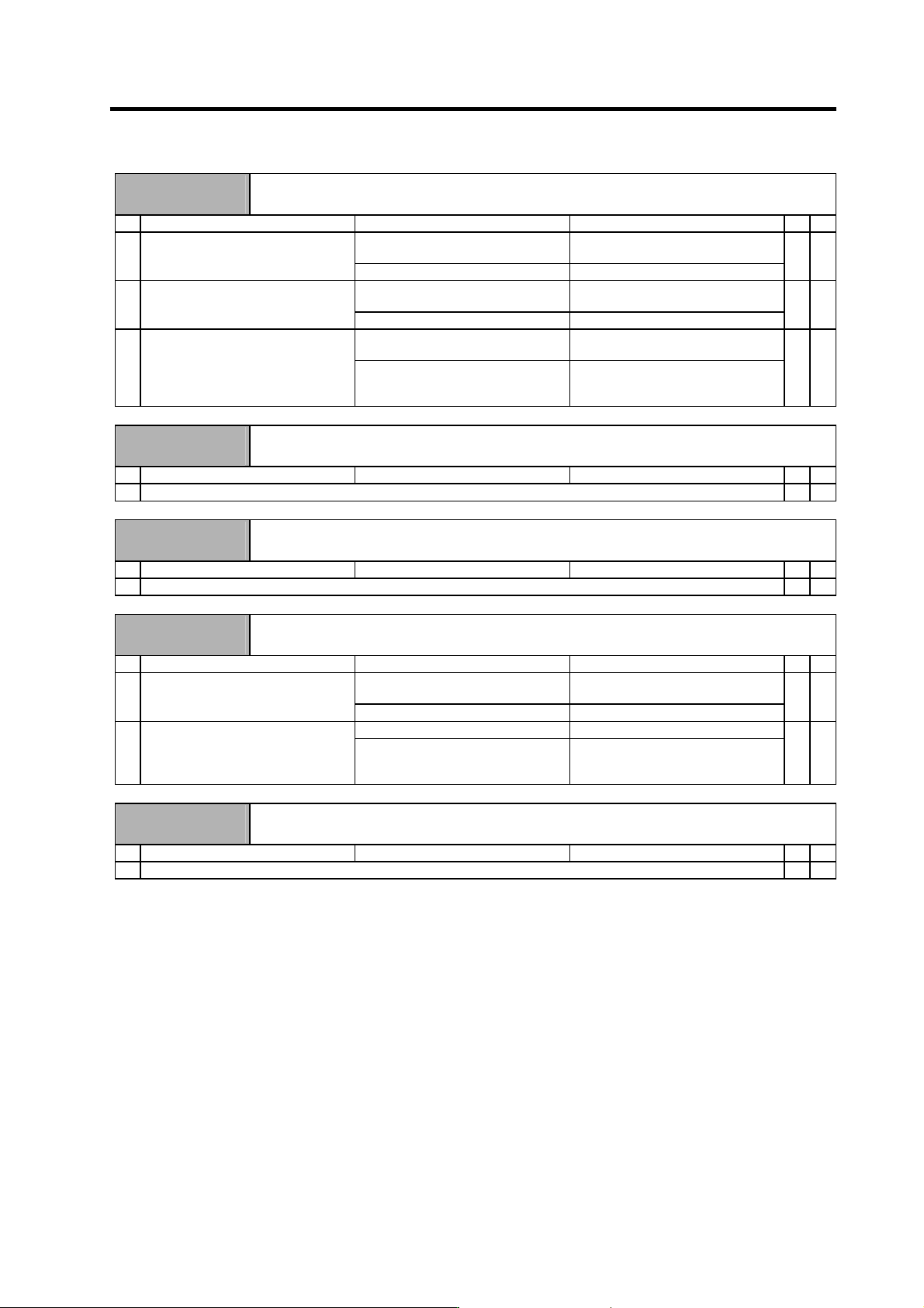
Warning No.
E7
NC emergency stop
Emergency stop was input from the NC.
Investigation details Investigation results Remedies SV SP
Emergency stop was input. The NC is in the emergency stop
state. (Normal)
1 Check whether NC emergency stop
was input.
Emergency stop was not input. Investigate item 2.
{ {
An alarm is occurring in another drive
unit.
Reset the alarm in the other drive
unit.
2 Check whether an alarm is occurring
in another drive unit.
An alarm is not occurring. Investigate item 3.
{ {
The terminator or battery unit's cable
is disconnected.
Correctly connect. 3 Check the NC communication bus
line.
The NC communication bus
connector (CN1A, CN1B) is loose, or
the cable is broken.
Correctly connect the cable.
{ {
Warning No.
E8
Auxiliary regeneration frequency over
Regeneration at the power supply performance limit is occurring frequently.
Investigation details Investigation results Remedies
CV CR
1 Check the alarm No. "75" items.
{
Warning No.
E9
Instantaneous power failure warning
An instantaneous power failure occurred.
Investigation details Investigation results Remedies
CV CR
1 Check the alarm No. "71" items.
{
Warning No.
EA
External emergency stop
The external emergency stop signal was input.
Investigation details Investigation results Remedies
CV CR
Use not allowed. Invalidate the external emergency
stop.
1 Check whether the specifications
allow use of the external emergency
stop.
Use is allowed. Investigate item 2.
{
24V is input. Replace the power supply unit. 2 Measure the input voltage of the
CN23 connector. (While emergency
stop is cancelled.)
24V is not input. Check whether the external
emergency stop cable is broken, or
check the external contact operation.
{
Warning No.
EB
Over-regeneration warning
The over-regeneration level is 80% or more.
Investigation details Investigation results Remedies
CV CR
1 Check the alarm No. "73" items.
{