bnp-b2365(eng)b.pdf - 第85页
2. Wiring and Connection 2 - 46 2-7-3 Wiring of an external emergency stop (1) External emergency stop setting Besides the emergency stop input from t he NC communication cable (CN1A, CN1B), double-protection when an eme…
2. Wiring and Connection
2 - 45
(3) Wiring
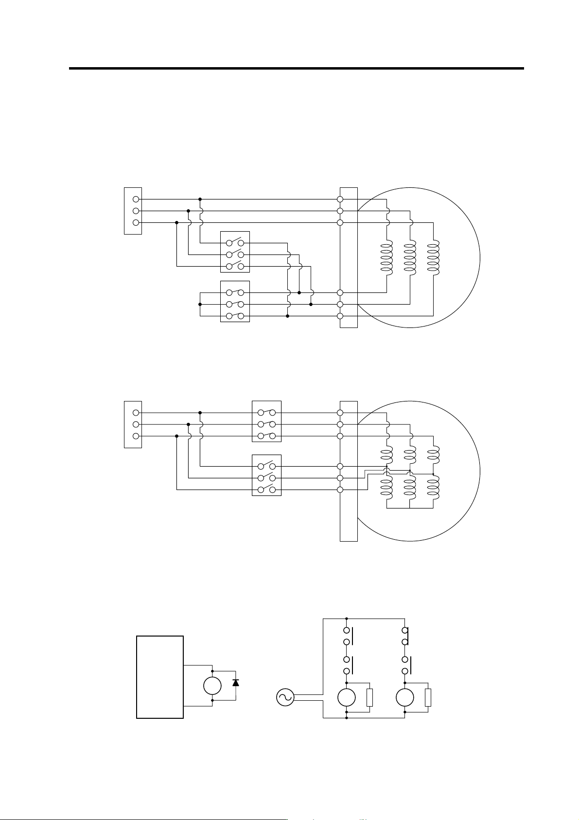
The illustration below shows the 2 types of changeover that occur after a coil changeover, (a) Y
(star) – ∆ (delta) changeover, and (b) Y (star) – Y (star) changeover. As shown in (c), one of the
contactors (MC1 or MC2) is turned ON and the other is turned OFF at all of the coil changeover
control circuits.
U
V
W
X
Y
Z
U
V
W
MC2
MC1
S
p
indle moto
r
Spindle drive unit
terminal block
MC1: Contactor to connect low-speed coil (Y-connection)
MC2: Contactor to connect high-speed coil (∆-connection)
(a) Y (star) - ∆ (delta) changeover circuit
U1
V1
W1
U2
V2
W2
U
V
W
MC1
Spindle motor
Spindle drive unit
terminal block
MC2
MC1: Contactor to connect low-speed coil (1st Y-connection)
MC2: Contactor to connect high-speed coil (2nd Y-connection)
(b) Y (star) - Y (star) changeover circuit
(c) Coil changeover control circuit (common)
Coil changeover relay control circuit
CN9-8
CN9-10
MDS-C1-SP
RA
MC1 SK
MC2
RA
S
T
MC2 SK
MC1
RA
2. Wiring and Connection
2 - 46
2-7-3 Wiring of an external emergency stop
(1) External emergency stop setting
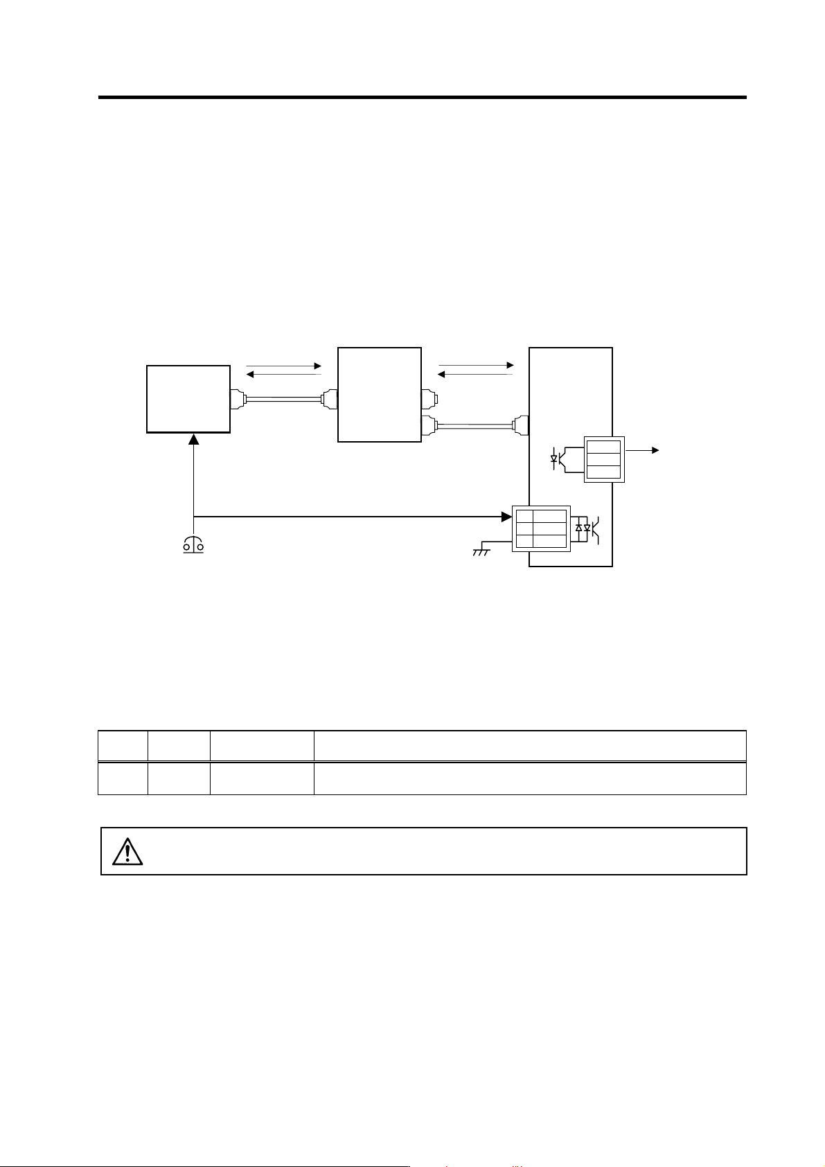
Besides the emergency stop input from the NC communication cable (CN1A, CN1B),
double-protection when an emergency stop occurs can be provided by directly inputting an external
emergency stop to the CN23 connector on the power supply unit. Even if the emergency stop is not
input from CNC for some reason, the contactors will be shut off by the external emergency stop
input from CN23 connector on the power supply unit.
[1] Connection
[2] Setting
When using the external emergency stop, the rotary switch on the front of the power supply unit and
the parameter (PTYP) of drive unit that controls the power supply must be set.
• Rotary switch setting: 4
• Parameter setting: Add "0040" to the setting of PTYP (Servo=SV036, Spindle=SP041).
Parameter settings
No.
Abbrevia-
tion
Parameter name Descriptions
SV036
SP041
PTYP Power supply type
When external emergency stop is validated, 0040 [hex] is added to PTYP for the drive
unit connected to the power supply unit.
CAUTION
The emergency stop signal input to the CNC side cannot be used as a substitute
for the external emergency stop function (CN23).
Mitsubishi NC
External emergency stop input
MDS-C1-V1/V2/SP
CN1A
CN4
MDS-C1-CV
CN4
CN1B
1 EMG1
2
N
C
3 EMG2
MC1
Emergency
stop
Alarm
Alarm
Contactor shutoff
command
CN23
MC1
L
21
L
11
SV1,2
SH21
FCUA-R000
FCUA-R000
SH21
Emergency
stop
2. Wiring and Connection
2 - 47
(2) Operation sequences of CN23 external emergency stop function
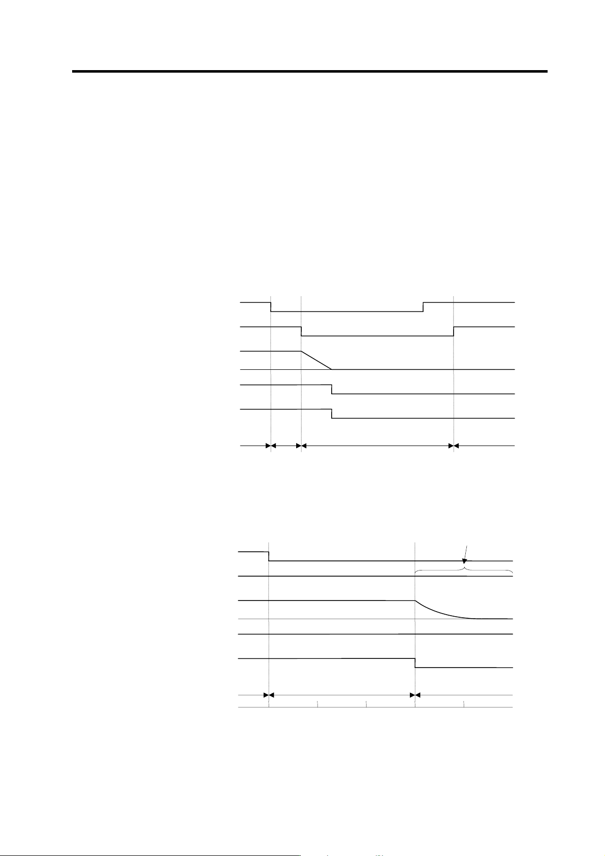
If only external emergency stop is input when external emergency stop valid is set in the
parameters (the emergency stop is not input in NC), an "In external emergency stop" (warning EA)
will be detected. At this time, the system itself does not enter an emergency stop status. (There will
be no deceleration control or dynamic brake stop.)
If a contactor shutoff command is not issued from the NC within 30 seconds after the external
emergency stop is input, the power supply unit output s contactor shutoff signal (MC1), and then it
shuts off the contactors, and a power supply error (alarm 6F) is detected simultaneously. If the
emergency stop is input from NC within 30 seconds, the warning EA replaces the "In NC
emergency stop" (warning E7). A normal emergency stop status will result if the contactor shutoff
command from the NC are further input.
Ready ON is possible even if CN23, an external emergency stop has been input when the
emergency stop is canceled, but an power supply error (alarm 6F) will occur after 30 seconds.
OFF
ON
External emergency stop input
(EMGX)
Servo drive unit st atus displ a y
Contact or cont rol terminal (MC)
ON
OFF
Motor speed
0
OFF
ON
Main emergency stop i nput
(EMG)
dx E7 EA
Deceleration control
Contactor control command
ON
OFF
Cx
→
dx
External emergency stop input sequences
OFF
ON
ON
OFF
0
OFF
ON
dx 6F, E7 EA
Dynamic brake
ON
OFF
The communication line enters an
emergency stop state by the output
from the servo.
0 30
Time (s)
External emergency stop input
(EMGX)
Servo drive unit status display
Contactor control terminal (MC)
Motor speed
Main emergency stop input
(EMG)
Contactor control command
When neither a main emergency stop nor contactor shutoff command is input