bnp-b2365(eng)b.pdf - 第152页
3. Setup 3 - 65 3-5 Setting the initial parameters for the spindle drive unit The spindle specification p arameters and spindle parameters m ust be set before the spindle system can be started up. The spindle related par…

3. Setup
3 - 64
3-4-2 Restrictions on absolute position control
When executing absolute position control, the following conditions must be satisfied. If not satisfied,
mechanical specifications and electrical specifications (such as resolution of the detector) must be
revised.
When executing incremental control, there are no particular restrictions on servo control. (Confirm with
the NC system side specifications.)
(1) For linear axis
The following conditions, Condition 1 an d 2, must be satisfied simultaneously.
(Condition 1)
2147
Length of stroke ≤
IUNIT
[m]
IUNIT = 2/NC command unit (µm)
1µm : IUNIT = 2, 0.1µm : IUNIT = 20
(Condition 2)
(a) For semi-closed loop control
PC1 x PIT
Length of stroke ≤ 2147 x
PC2 x RNG2
[m]
(b) For full-closed loop control
PIT
Length of stroke ≤ 2147 x
RNG1
[m]
(Note) Even during the full-closed loop control, when the MP scale is used, restrictions are
applied with the condition (a), as well.
(2) For rotary axis
The following conditions must be satisfied.
2147000
PC2 ≤
RNG2
x PC1

3. Setup
3 - 65
3-5 Setting the initial parameters for the spindle drive unit
The spindle specification parameters and spindle parameters must be set before the spindle system
can be started up. The spindle related parameters are input from the NC. The input method differs
according to the NC being used, so refer to each NC Instruction Manual.
3-5-1 Spindle specification parameters
The configuration of these parameters depends on the NC, so refer to each NC Instruction Manual. The
following table shows the configuration of the M60S and E60 Series NC.
M60S
Series
No.
Abbrev. Parameter name Details
Setting rang e
(Unit)
3001
3002
3003
3004
slimit 1
2
3
4
Limit rotation
speed
Set spindle rotation speed for maximum motor rotation speed with gears
00, 01, 10, 11.
(Set the spindle speed for the S analog output 10V.)
0 to 99999
(r/min)
3005
3006
3007
3008
smax 1
2
3
4
Maximum rotation
speed
Set maximum spindle rotation speed with gears 00, 01, 10, 11.
Set to slimt ≥ smax.
By comparing the S command value and the value of gear 1 to 4, a spindle
gear shift command will be output automatically.
0 to 99999
(r/min)
3009
3010
3011
3012
ssift 1
2
3
4
Shift rotation
speed
Set spindle speed for gear shifting with gears 00, 01, 10, 11.
(Note) Setting too large value may cause a gear nicks when changing
gears.
0 to 32767
(r/min)
3013
3014
3015
3016
stap 1
2
3
4
Tap rotation speed
Set maximum spindle rotation speed during tap cycle with gears 00, 01,
10, 11.
0 to 99999
(r/min)
3017
3018
3019
3020
stapt 1
2
3
4
Tap time constant
Set time constants for constant inclination synchronous tap cycles for
gears 00, 01, 10, 11 (linear acceleration/deceleration pattern).
1 to 5000 (ms)
3. Setup
3 - 66
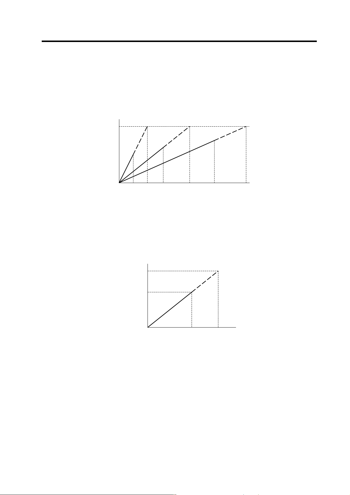
<Relation of spindle limit rotation speed and spindle maximum rotation speed>
The spindle rotation speed which can be attained at the spindle motor's maximum rotation speed is
set for the limit rotation speed (slimt). This value is obtained by multiplying the gear ratio on the
spindle motor maximum rotation speed (SP017). Set the maximum rotation speed (smax) when
the rotation speed is to be limited according to the machine specifications, such as the spindle gear
specifications. Up to four value can be set for gear changeover.
<Relation of tap time constant and actual acceleration/deceleration time constant>
(For constant inclination synchronous tap cycle)
Set the acceleration time up to the tap rotation speed (stap) in the tap time constant (stapt).
Acceleration/deceleration is carried out at the same inclination for all speed commands. Up to four
values can be set for gear changeover.
SP017
Spindle motor rotation speed
(r/min)
0
smax1 slimt1 smax2 smax(n)slimt2 slimt(n)
Spindle rotation speed (r/min)
stap(n)
0
Actual time
stapt(n)
Time (ms)
Actual
command
Spindle speed (r/min)