bnp-b2365(eng)b.pdf - 第227页
4. Servo Adjustment 4 - 28 No. Abbrev . Parameter name Explanation Setting range F E D C B A 9 8 7 6 5 4 3 2 1 0 aflt zrn2 afse ovs lmc omr zrn3 vfct upc vcnt bit Meaning when "0" is set Meaning when "1&qu…
4. Servo Adjustment
4 - 27
(5) Setting and adjusting LMC compensation type 3
LCM compensation type 3 can be used to accommodate quadrant projection changes that
accompany feed rate and circular radius changes which could not be accommodated by LCM
compensation type 2. In this case, on a machine model where the travel direction is reversed, the
viscosity component is also considered in addition to the friction, with compensation occurring in
accordance with the changes in the cutting conditions.
Adjust Compensation parameter (SV016, SV041), a basis of compensation, while measuring
roundness at low speed. Then adjust viscous coefficient (SV086) while measuring roundness at
high speed.
LMC compensation type 3 parameter adjustments should be made while performing a machine
end roundness measurement such as a DDB measurement, etc.
<Adjustment method>
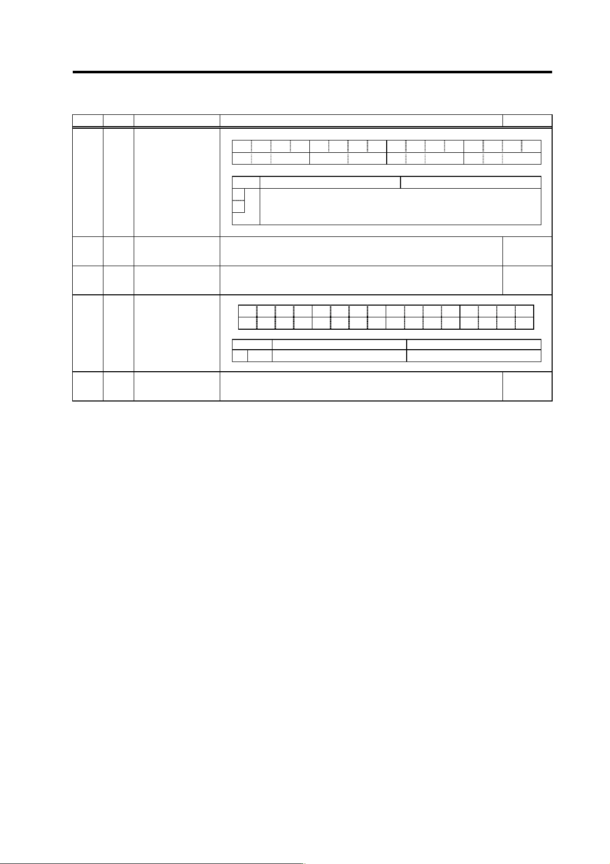
[1] Set the bit1=1 to servo function selection 5 (SV082). (The LMC compensation type 3 will start).
[2] Set a value double the friction torque to the lost motion compensation 1 (SV016). The SV016 setting
value will be used for compensation in the positive and negative directions when the lost motion
compensation 2 (SV041) is 0.
[3] Set the initial value, 1000 to the lost motion compensation viscous coefficient (SV086).
[4] Perform a roundness measurement at such speed as radius R=100mm and feedrate F=1000mm/min
and adjust SV016 value.
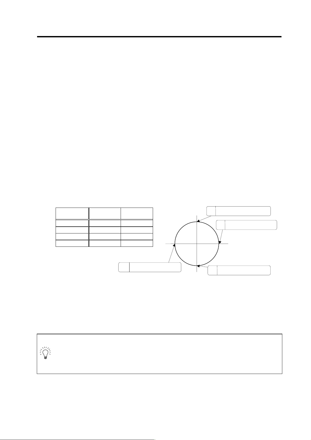
[5] Set SV041, when changing the compensation amount in the direction for compensation. The setting
of the compensation direction is shown below with the setting of CW/CCW in the NC parameter. If
compensating only one direction, set –1 to the side not to be compensated.
Compensation
point
CW CCW
A X axis: SV041 X axis: SV016
B Y axis: SV016 Y axis: SV041
C X axis: SV016 X axis: SV041
D Y axis: SV041 Y axis: SV016
[6] Perform a roundness measurement at such speed as radius, R=100mm and feedrate,
F=5000mm/min. (Select a condition to be used for the actual cutting according to the machine's
specification.) Adjust viscous coefficient (SV086) by reducing it gradually to have minimum quadrant
protrusion.
[7] After adjusting SV086, verify its accuracy by performing roundness measurement at low speed again.
POINT
1. As the acceleration of circular feed increases, the quadrant protrusion tends to
get larger. Therefore, the quadrant protrusion gets larger as the circular feedrate
increases for the same radius and as radius gets smaller for the same feedrate.
2. Torque offset (SV032) does not work for LMC compensation type 3.
3. Always set 0 to the lost motion compensation timing (SV039:LMCD).
+Y
-Y
+X
-X
A
The X axis command direction
chan
g
es from + to -.
D
The Y axis command direction
changes from + to -.
B
The Y axis command direction
changes from - to +.
C
The X axis command direction
changes from - to +.
4. Servo Adjustment
4 - 28
No. Abbrev. Parameter name Explanation Setting range
F E D C B A 9 8 7 6 5 4 3 2 1 0
aflt zrn2 afse ovs lmc omr zrn3 vfct upc vcnt
bit Meaning when "0" is set Meaning when "1" is set
8 Set the compensation amount with SV016 (LMC1) and SV041 (LMC2).
9
lmc
00: Lost motion compensation stop 10: Lost motion compensation type 2
01: Lost motion compensation type 1 11: Setting prohibited
SV027 SSF1
Servo function
selection 1
SV016 LMC1
Lost motion
compensation 1
Set the compensation amount based on the stall (rated) current of the motor.
The standard setting is double of the friction torque. Setting to "0" means the
compensation amount is zero.
-1 to 200
(Stall [rated]
current %)
SV041 LMC2 Lost motion
compensation 2
Set this with SV016 (LMC1) only when you wish to set the lost motion
compensation amount to be different depending on the command directions.
Set to "0" as a standard.
-1 to 200
(Stall [rated]
current %)
F E D C B A 9 8 7 6 5 4 3 2 1 0
obshj lmc3 lmct
bit Meaning when "0" is set Meaning when "1" is set
1
lmc3
Lost motion compensation 3 stop Lost motion compensation 3 start
SV082
SSF5 Servo function
selection5
SV086 LMCc Lost motion
compensation
viscous coefficient
Set the machine system's viscous coefficient when using lost motion
compensation type 3.
0 to 32767
4. Servo Adjustment
4 - 29
4-3-6 Improvement of overshooting
The phenomenon when the machine position goes past or exceeds the command during feed
stopping is called overshooting. Overshooting is compensated by overshooting compensation
(OVS compensation).
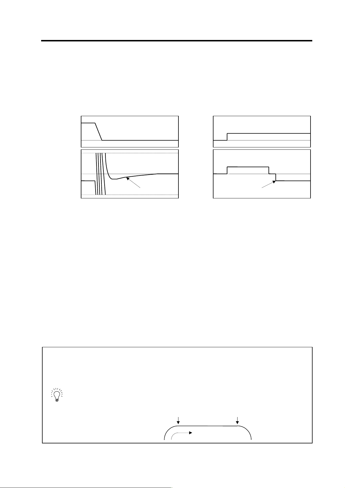
Overshooting occurs due to the following two causes.
[1] Machine system torsion: Overshooting will occur mainly during rapid traverse settling
[2] Machine system friction: Overshooting will occur mainly during one pulse feed
Either phenomenon can be confirmed by measuring the position droop.
[1] Overshooting during rapid tr a verse settling [2] Overshooting during pulse feed
(1) Overshooting compensa tion (OVS compensation)
In OVS compensation, the overshooting is suppressed by subtracting the torque command set in
the parameters when the motor stops. There are three types of OVS compensation. Type 3 is the
standard method. (Types 1 and 2 are for compatibility with older models, and thus explanations
have been omitted.)
OVS compensation type 3 has a compensation effect for the overshooting during either rapid
traverse settling or pulse feed. To compensate overshooting during feed forward control, refer to
the following section "(2) Adjusting for feed forward control".
<Setting and adjustment methods>
[1] Set the servo function selection 1 (SV027: SSF1)/bit A, B. (OVS compensation type 3 will start.)
[2] Observe the position droop waveform using the D/A output, and increase the overshooting
compensation 1 (SV031: OVS1) value 1% at a time. Set the smallest value where the overshooting
does not occur. If SV042 (OVS2) is 0, the overshooting will be compensated in both the
forward/reverse directions with the OVS1 setting value.
[3] If the compensation amount is to be changed in the direction to be compensated, set the + direction
compensation value in OVS1 and the - direction compensation value in OVS2. If only one direction is
to be compensated, set the side not to be compensated as -1. The compensation direction setting will
be as reversed with the NC parameter CW/CCW setting.
POINT
1. When either parameter SV031: OVS1 or SV042: OVS2 is set to 0, the same
amount of compensation is carried out in both the positive and negative
direction, using the setting value of the other parameter (the parameter not
set to 0).
2. To compensate in only one direction, set -1 in the parameter (OVS1 or
OVS2) for the direction in which compensation is prohibited.
3. For contour cutting, the projection at the arc end point is compensated with
OVS compensation. LMC compensation is carried out at the arc starting
point.
Cutting direction
LMC compensation
OVS compensation
0
Position
command
0
Position
droop
Time
Overshoo
t
0
Speed
FB
0
Position
droop
Time
Overshoot