bnp-b2365(eng)b.pdf - 第35页
1. Installation 1 - 19 1-4-3 Spindle end PLG (1) Part configuration The detector is configured of an encoder (Sensor section and PCB section) and detection gears. The encoder section can be separated with an inte rmediat…
1. Installation
1 - 18
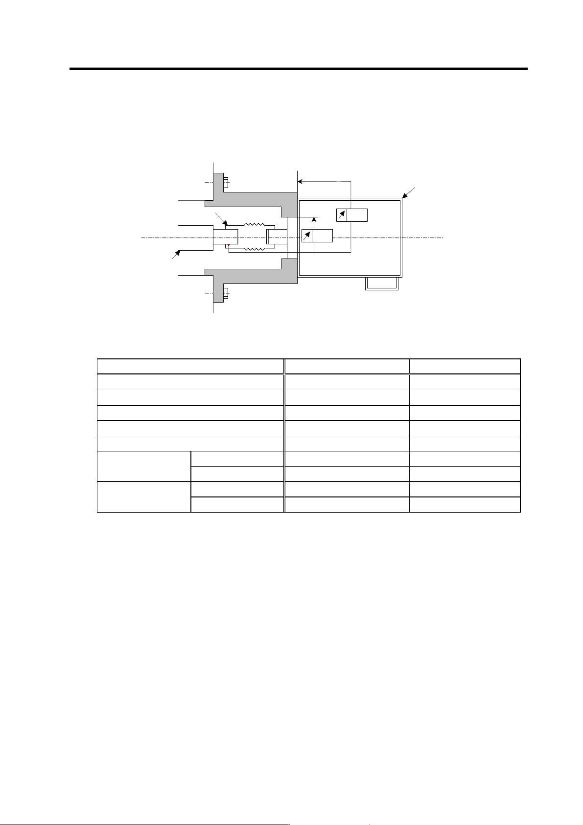
1-4-2 Spindle end detector
To maintain the detector life and performance, a flexible coupling should be used to couple the spindle
end detector and C-axis detector with the spindle.
Detector
0.02
0.02
Opposite detector shaft
side
Flexible coupling
Detector and coupling installation accuracy
Recommended coupling
Recommendation 1 Recommendation 2
Manufacturer Tokushu Seiko Eagle
Model Model M1 FCS38A
Resonance frequency 1374Hz 3515Hz
Position detection error 0.8×10⁻³° 1.2×10⁻³°
Tolerable speed 20000r/min 10000r/min
Core deviation 0.7mm 0.16mm
Mis-alignment
Angle displacement
1.5° 1.5°
Max. length 74.5mm 33mm
Outline dimensions
Max. diameter
ø57mm ø38mm
Refer to the coupling catalog, etc., for details on the coupling.
1. Installation
1 - 19
1-4-3 Spindle end PLG
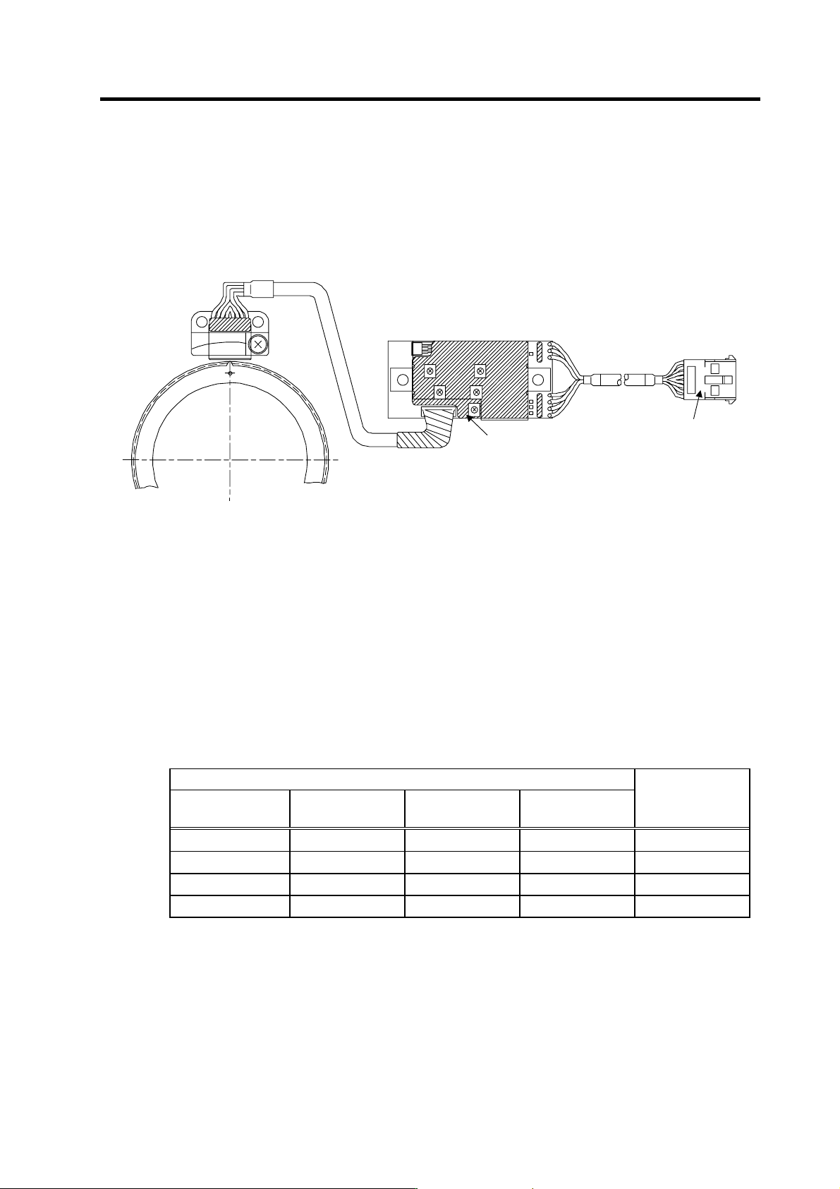
(1) Part configuration
The detector is configured of an encoder (Sensor section and PCB section) and detection gears.
The encoder section can be separated with an intermediate connector, but a type with the same
serial No. must be used in combination. The serial No. is indicated on the intermediate connector of
the sensor section and the output connector of the PCB section.
G
B
Z
A
VR1
VR2
VR3
VR4
VR5
Detection
gears
Sensor section
PCB section
Intermediate
connecto
r
Output connector
Serial No. indication
Encoder
Spindle end PLG
These are precision parts, and require care when handling. Do not apply an excessive force on the
sensor's detection surface, as this could result in faults. Do not pull and apply a load on the lead
wires. Make sure that foreign matters (iron chips, etc.) do not get on the sensor's detection surface
or detection gears. If any foreign matter should get on these parts, carefully remove while taking
care not to damage the parts. When handling the detection gears, take care not to damage or
deform the teeth.
(2) Installing the detection gears and sensor section
[1] Install the detection gears so that the first gear's teeth side (Z phase) face the sensor's lead
side.
[2] The detection gears and shaft or sleeve should be fixed with shrinkage fitting. Refer to the
following table for the shrinkage fitting values. The detection gears should be heated evenly
between 120 and 150°C using an electric furnace, etc.
Detection gear shrinkage fitting values
Detection gear specifications
Part type
No. of teeth
Outer diameter
(mm)
Inner diameter
(mm)
Shrinkage fitting
(mm)
MU1450N2137 128 ø52 ø40 0.02 to 0.04
MU1450N2730 180 ø72.8 ø55 0.03 to 0.055
MU1450N2236 256 ø103.2 ø80 0.03 to 0.055
MU1450N2534 512 ø205.6 ø140 0.05 to 0.085
1. Installation
1 - 20
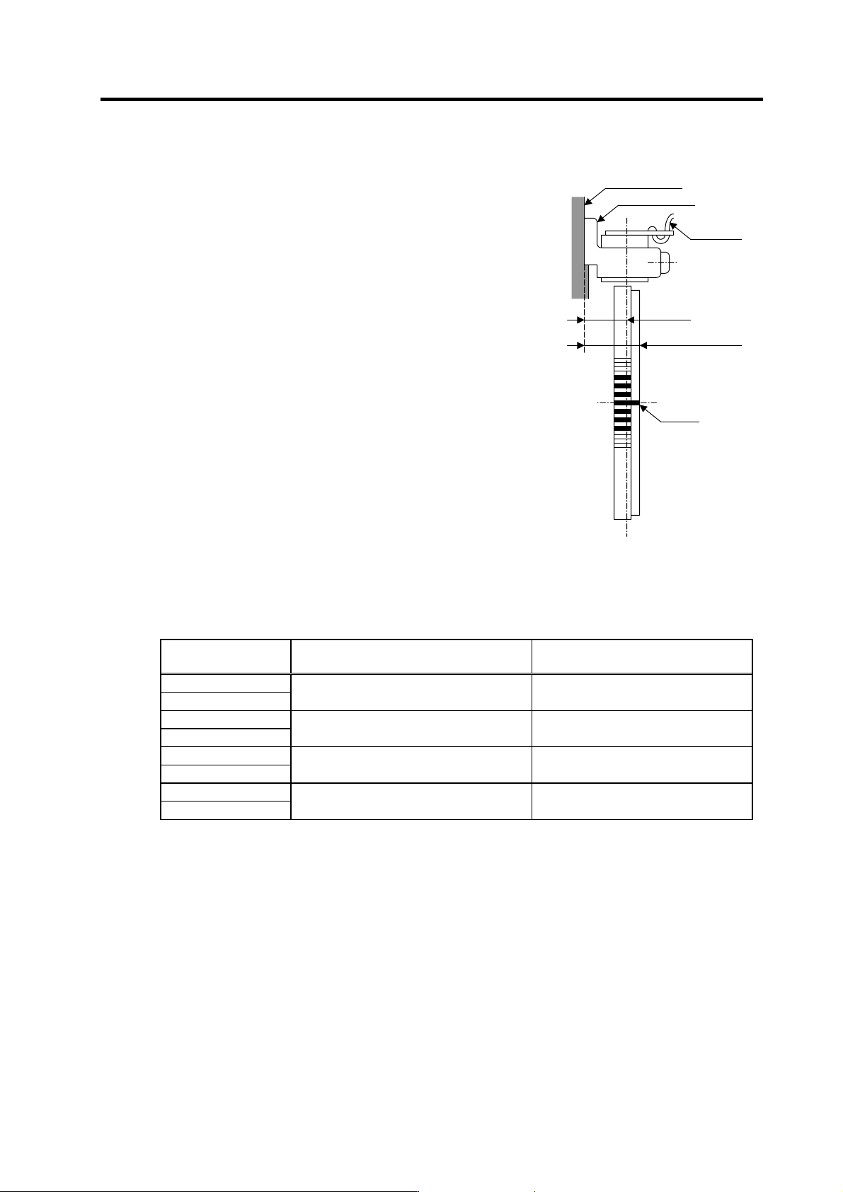
[3] Keep the deviation of the sensor center and detection
gear center to ±0.25mm or less. If the center deviation
cannot be directly measured, set so that the dimension
from the sensor installing surface to the edge of the
detection gears is 22.5±0.25mm.
[4] Keep the deflection of the outer diameter, when the
detection gears are installed on the shaft, to 0.02mm or
less.
[5] To remove a detection gear fixed with shrinkage fitting,
use the screw holes opened in the axial direction for
pulling (two M5 screw holes or two M8 screw holes), or
push the end with a jig. Carry out this work carefully.
Applying excessive force when pulling out the gears
could cause the inner diameter of the detection gears to
deform.
[6] Before reusing detection gears which have been
removed, always measure the inner diameter dimensions,
and carefully check that the inner diameter is not
deformed, and that the sufficient tightening amount can
be secured. Do not reuse the detection gears if the inner
diameter is deformed, or if any abnormality such as
damage to the teeth is found.
[7] A notched fitting section and mounting screw hole are
provided on the machine as shown in the following
drawing. Contact the R section of the sensor installation
seat against this and, install the sensor. The outline dimensions of the notched fitting section
are shown in the following table.
Installing the sensor section
Encoder part type
Sensor installation seat's
R dimensions (mm)
Notched fitting section's
outer diameter (mm)
TS1860N2275 +0.200
TS1860N2276
R35.5 ø71
+0.180
TS1860N2777 +0.200
TS1860N2775
R45 ø90
+0.180
TS1860N2171 +0.200
TS1860N2174
R61 ø122
+0.175
TS1860N2571 +0.200
TS1860N2572
R112.5 ø225
+0.170
16.5mm
22.5mm
±.25mm
Sensor installation surface
Sensor installation seat
Lead wire
First tooth
Installing the detection gears