bnp-b2365(eng)b.pdf - 第57页
2. Wiring and Connection 2 - 18 2-4-2 Connecting the full-closed loop system Refer to section "2-4-1 Connecting the servomot or" for details on connecting the each motor type. (1) Connecting the ball screw end …
2. Wiring and Connection
2 - 17
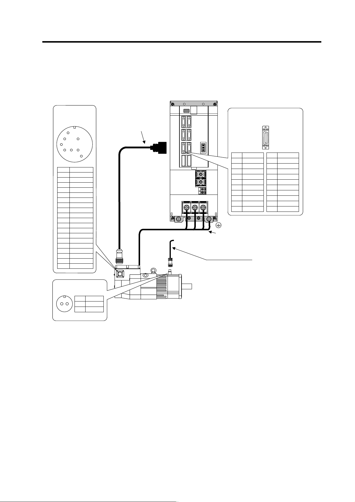
(7) Connecting the HA-LF11K2(B)-S8/HA-LF15K2(B)-S8
Pin Name
A
B
C
D
E BAT
F
G
H SD
J SD*
K RQ
L RQ*
M
N FG
P
R LG(GND)
S P5(+5V)
T
U
V
MS3102A22-14P
E
J
K
H
N
L
R
S
MDS-C1-V1
Name
LG
SD*
RQ*
P5(+5V)
P5
(
+5V
)
Pin
11
12
13
14
15
16
17
18
19
20
Name
LG
SD
RQ
BAT
P5
(
+5V
)
Pin
1
2
3
4
5
6
7
8
9
10
MS3102A10SL-4P
A
B
Name
B1
B2
Pin
A
B
U V W
Detector connecto
r
Pin No.
Detector connector : CN2
No.1
No.10
No.11
No.20
Brake connector
Option cable : CNV12
(Refer to Appendix 1 for details
on the cable tre atment.)
Max. 30m
Power wire and grounding wire
(Refer to Specification manual for details
on selecting the wire.)
CN2
(Refer to section
"2-6 Wiring of the motor
brake" for details.)
Motor brake wiring
These are 24VDC, and have
no polarity.
2. Wiring and Connection
2 - 18
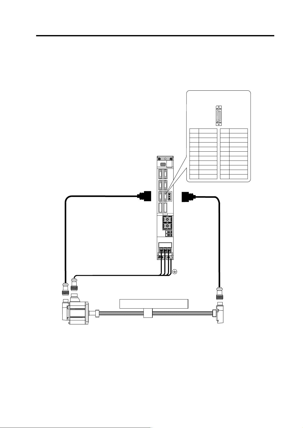
2-4-2 Connecting the full-closed loop system
Refer to section "2-4-1 Connecting the servomotor" for details on connecting the each motor type.
(1) Connecting the ball screw end detector
MDS-C1-V1
CN2
Servomotor
CN3
CNV13
Name
LG
SD*
RQ*
P5(+5V)
P5
(
+5V
)
Pin
11
12
13
14
15
16
17
18
19
20
Name
LG
SD
RQ
BAT
P5
(
+5V
)
Pin
1
2
3
4
5
6
7
8
9
10
CNV12
Table
U V W
Pin No.
Detector connector : CN3
No.1
No.10
No.11
No.20
Max. 30m
2. Wiring and Connection
2 - 19
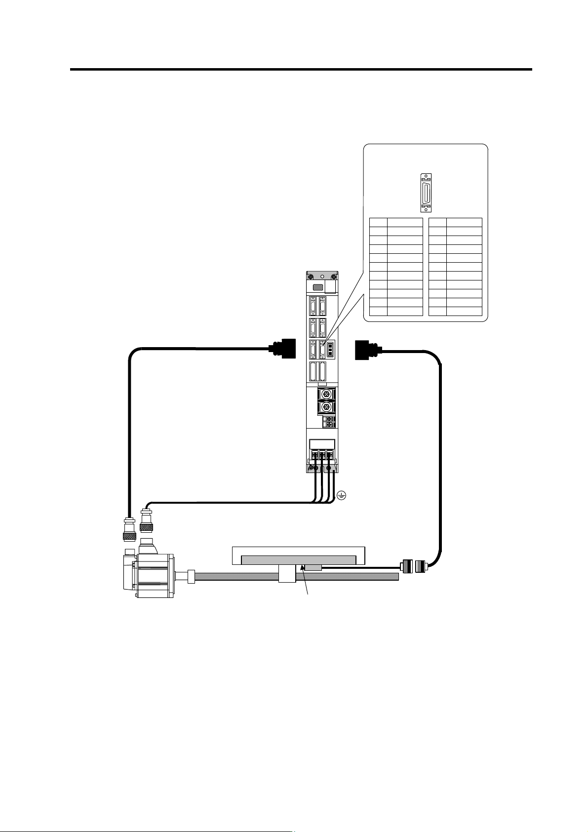
(2) Connecting the linear scale (for oblong wave data output)
MDS-C1-V1
CN2 CN3
Name
LG
A*
B*
Z*
P5(+5V)
P5
(
+5V
)
Pin
11
12
13
14
15
16
17
18
19
20
Name
LG
A
B
Z
BAT
P5
(
+5V
)
Pin
1
2
3
4
5
6
7
8
9
10
CNV12
Servomotor
Table
U V W
Pin No.
Detector connector : CN3
No.1
No.10
No.11
No.20
Max. 30m
Linear scale