bnp-b2365(eng)b.pdf - 第48页
2. Wiring and Connection 2 - 9 (2) When using tw o or more pow er supply uni ts within a single NC communication bus system Two or more power supply units may be required within a single NC communication bus system if th…
2. Wiring and Connection
2 - 8
2-3 NC and drive unit connection
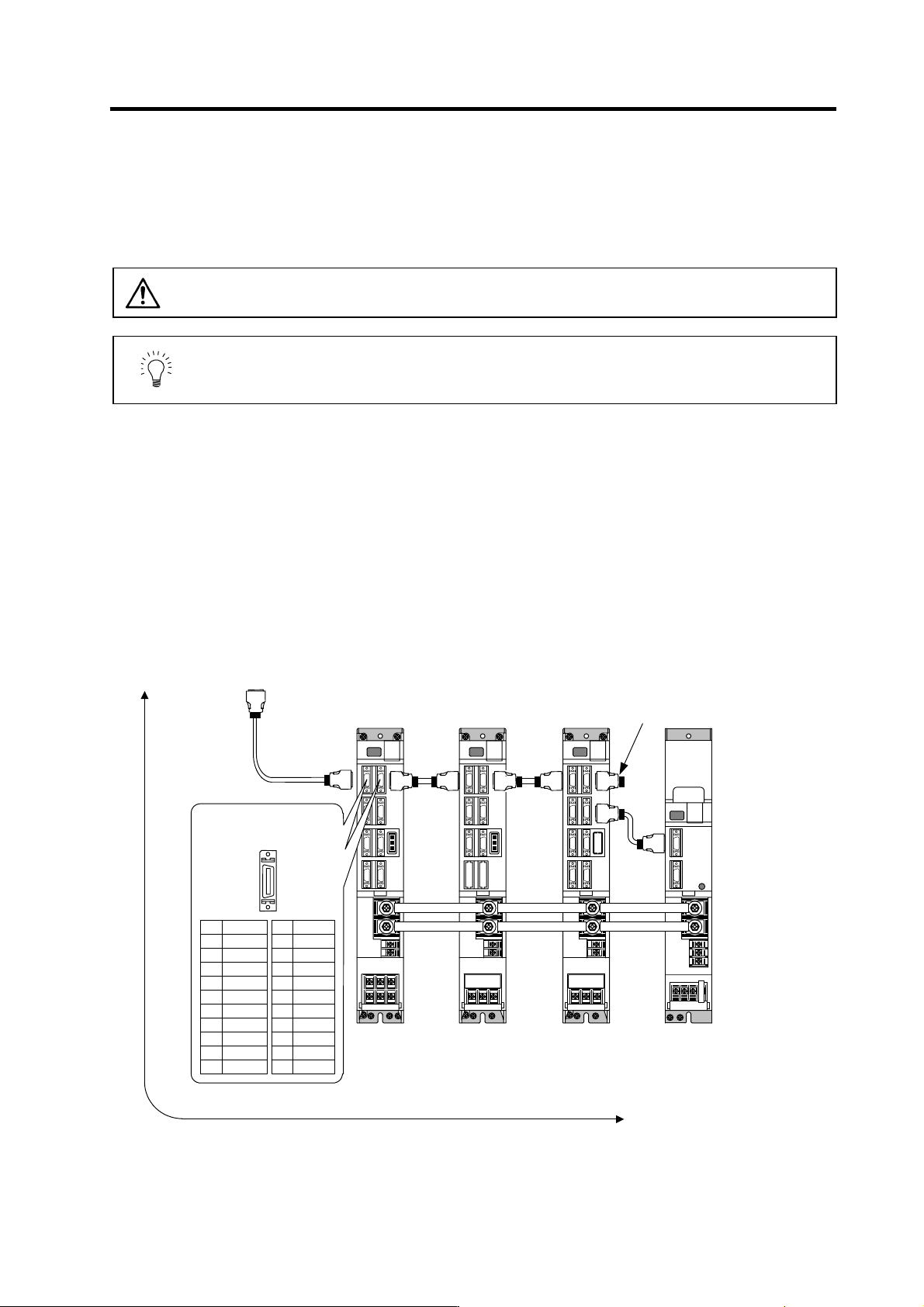
The NC bus cables are connected from the NC to each drive unit so that they run in a straight line from
the NC to the terminal connector (battery unit). And up to 7 axes can be connected per system.
Note that the number of connected axes is limited by the NC.
CAUTION
Wire the SH21 cable between the NC and drive unit so that the distance
between the NC and terminal connector (battery unit) is within 30m.
POINT
Axis Nos. are determined by the rotary switch for setting the axis No. (Refer to
section "3-1-1 Setting the rotary switch".) The axis No. has no relation to the
order for connecting to the NC.
(1) When using one power supply unit
Connect the largest-capacity spindle drive unit to the final axis of the NC communication bus in
order to control the power supply unit. The spindle drive unit must be installed adjacent to the power
supply unit. In the system with servo only, a servo drive unit for controlling unbalance axis must be
installed in the same manner in the same way.
< Connection >
CN1A : CN1B connector on NC or previous stage's drive unit
CN1B : CN1A connector on next stage's drive unit or terminal connector (battery unit)
CN4 : Connector for communication between power supply unit (master side) and drive unit
Connect to the battery unit with a
terminal connector or SH21 cable.
Refer to the
instruction manual
of each NC for
details.
Max. len
g
th of 30m from the NC to terminal connector or batter
y
unit.
CN1A
SH21 cable
MDS-C1-SP
4th axis (final axis)
MDS-C1-V1
3rd axis
Connected
to the NC
MDS-C1-CV MDS-C1-V2
1st/2nd axis
CN1B CN1A
CN1B
CN1A
CN1B
CN4
CN4
Pin No.
CN1A/CN1B
No.1
No.10
No.11
No.20
Name
GND
RD*
AL
SD*
GND
GFO
EMG*
P5
(
+5V
)
11
12
13
14
15
16
17
18
19
20
Name
GND
RD
AL
SD
GND
GFO
EMG
BAT
P5
(
+5V
)
1
2
3
4
5
6
7
8
9
10
Connection when using one power supply unit
2. Wiring and Connection
2 - 9
(2) When using two or more power supply units within a single NC communication bus system
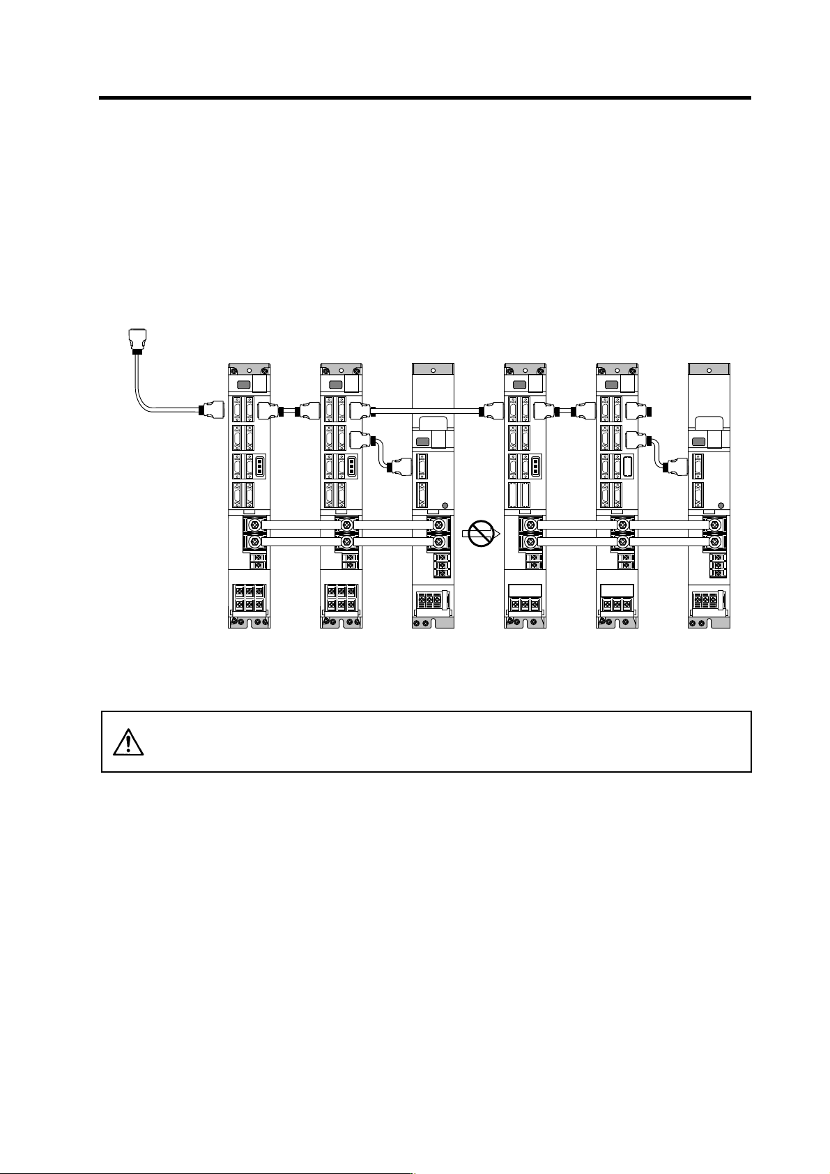
Two or more power supply units may be required within a single NC communication bus system if
the spindle drive unit capacity is large. The drive unit receiving power (L+, L-) from each power
supply unit must always have NC communication bus connection at the NC side of each power
supply unit. In the NC communication bus connection example below, power supply [1] cannot
supply power (L+, L-) to the 5th axis servo drive unit.
For basic connection information, refer to "(1) When using one power supply unit".
Connections when using two power supply units within a single NC communication bus system
CAUTION
The drive unit receiving power (L+, L-) from each power supply unit must always
have NC communication bus connection at the NC side of each power supply
unit.
CN1A
SH21 cable
MDS-C1-SP
6th axis
(CV control axis)
MDS-C1-V1
5th axis
Connected
to the NC
MDS-C1-CV
[2]
MDS-C1-V2
1st/2nd axis
CN1B CN1A
CN1B
CN1A
CN1B
CN1A
CN1B
CN4
CN4
CN4
CN4
MDS-C1-V2
3rd/4th axis
(CV control axis)
MDS-C1-CV
[1]
Power
cannot be
supplied
2. Wiring and Connection
2 - 10
(3) When using one power supply shared unit by two NC communication bus systems
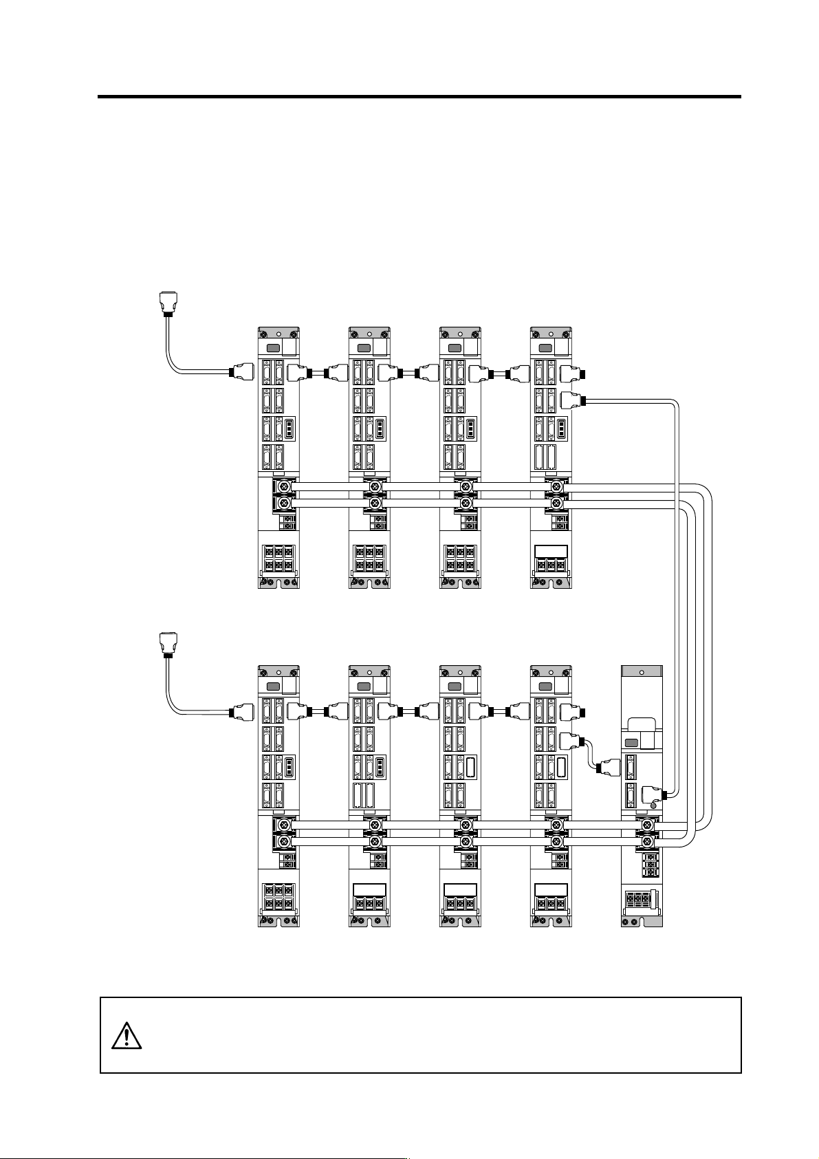
In systems employing a number of small-capacity drive units, a single power supply unit can be
shared by two NC communication bus systems. In this case, a power supply control axis must be
set for each axis of each NC communication bus.
For basic connection information, refer to "(1) When using one power supply unit".
Connections when using one power supply shared by two NC communication bus systems
CAUTION
If the two NC communication bus systems include a spindle drive unit, connect
the power supply unit's CN4 connector to the CN4 connector of the largest-
capacity spindle drive unit. If there is no spindle drive unit, connect to the
unbalance-axis servo drive unit.
MDS-C1-SP
12th axis
(CV control axis)
MDS-C1-V1
7th axis
(CV control axis)
CN1A
Connected to the NC
(System No.1)
MDS-C1-CV
(shared)
MDS-C1-V2
1st/2nd axis
CN1B CN1A
CN1B
CN4
CN4
MDS-C1-V2
3rd/4th axis
MDS-C1-V2
5th/6th axis
CN1B
CN1A
CN1B
CN1A
MDS-C1-V2
8th/9th axis
CN1B CN1A
MDS-C1-V1
10th axis
MDS-C1-SP
11th axis
CN1A
Connected to the NC
(System No.2)
CN1B
CN1A
CN1B
CN1A
CN1B
CN4
CN9