bnp-b2365(eng)b.pdf - 第249页
5. Spindle Adjustment 5 - 4 5-1-3 Setting the output magnification (1) Meter output (Da ta No. 0) With meter output, the output channel is fixed, and the output voltage range is 0 to 10V in the positive range. Set the ma…
5. Spindle Adjustment
5 - 3
5-1-2 Setting the output data
No. Abbr. Parameter name Explanation
SP253 DA1NO
D/A output channel 1 data No.
Input the No. of the data to be output to each D/A output channel.
SP254 DA2NO
D/A output channel 2 data No.
No. Output data Ori ginal data unit
Output magnification
standard setting value
(SP255, SP256)
Output unit for
standard setting
Output
cycle
ch1: Speedometer output 10V=max. speed (Zero=0V) 0
Depends on maximum
speed
3.55ms
0
ch2: Load meter output 10V=120% load (Zero=0V) 0 30-minute rating 12%/V 3.55ms
1 –
2 Current command Rated 100%=4096 8 30-minute rating 20%/V 3.55ms
3 Current feedback Rated 100%=4096 8 30-minute rating 20%/V 3.55ms
4 Speed feedback r/min 13 500rpm/V 3.55ms
5 –
6
Position droop
(lower order 16bit)
0.001deg=64 10 (10.24) 0.01deg/V 888µs
7
Position droop
(higher order 16bit)
1deg=(64000÷65536)
671 10deg/V 888µs
8
Feedrate (F∆T)
(lower order 16bit)
0.001deg=64
173
(at 3.5ms communication)
10deg/min/V 888µs
9
Feedrate (F∆T)
(higher order 16bit)
1deg=(64000÷65536)
629
(at 3.5ms communication)
500rpm/V 888µs
10
Position command
(lower order 16bit)
0.001deg=64 10 (10.24) 0.01deg/V 888µs
11
Position command
(higher order 16bit)
1deg=(64000÷65536)
19 (18.64) 360deg/V 888µs
12
Position FB
(lower order 16bit)
0.001deg=64 10 (10.24) 0.01deg/V 888µs
13
Position FB
(higher order 16bit)
1deg=(64000÷65536)
19 (18.64) 360deg/V 888µs
80 Control input 1
81 Control input 2
82 Control input 3
83 Control input 4
84 Control output 1
HEX Bit correspondence 3.55ms
85 Control output 2
86 Control output 3
87 Control output 4
5. Spindle Adjustment
5 - 4
5-1-3 Setting the output magnification
(1) Meter output (Data No. 0)
With meter output, the output channel is fixed, and the output voltage range is 0 to 10V in the
positive range. Set the magnification with the following parameters. Also, low path filter can be set
on the load meter output.
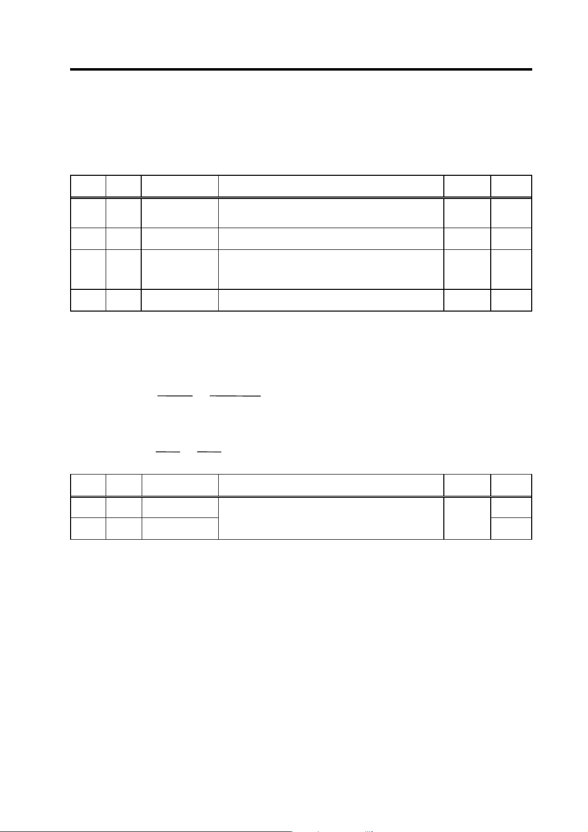
No. Abbr. Parameter name Details
Setting
range
Standard
SP017 TSP* Maximum motor
speed
Set the maximum spindle motor speed.
When SP249=0, the motor speed will be the motor rotation
speed at the speedometer 10V output.
1 to 32767
(r/min)
6000
SP094 LMAV* Load meter output
filter
Set the filter time constant of load meter output.
When "0" is set, a filter time constant is set to 100ms.
0 to 32767
(2ms)
0
SP249 SMO Speedometer speed Set the motor rotation speed when the speedometer 10V is
output.
When set to "0", this parameter becomes the same as SP017
(TSP).
0 to 32767
(r/min)
0
SP250 LMO Load meter voltage Set the voltage when the load meter 120% is output. When set
to "0", this becomes 10V.
0 to 10
(V)
0
(2) Internal data output (D at a No. 1 to 13)
Normally, the standard setting value is set for the output magnification (SP255, SP256). When
"0" is set, the magnification will be the same as "256".
DATA ×
SP255
256
×
10 [V]
256
(
8 bit
)
+ 5 [V] (offset) = Output voltage [V]
(Example) To output current FB at a 30-minute stall rating 20%/V unit (SP253=3, SP255=8)
819.2 ×
8
256
×
10
256
+ 5 = 6 [V]
No. Abbr. Parameter name Details
Setting
range
Standard
SP255 DA1MPY DA output channel 1
magnification
0
SP256 DA2MPY DA output channel 2
magnification
Set the output magnification with a 1/256 unit.
When "0" is set, the magnification will be the same as "256".
-32768 to
32767
(1/256-fold)
0
5. Spindle Adjustment
5 - 5
(3) Control signal output (Data No. 80 to 87)
A hexadecimal display is converted into a decimal and output. The method of calculating the
magnification is the same as (2). The status cannot be output for each bit, so output the status for
all 16 bits.
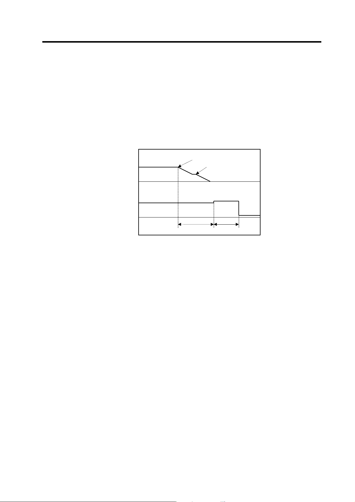
(Example) Orientation indexing control
With orientation indexing control, the following operations of the "Control output 4" can be
observed as shown on the right:
bit4: Orientation completed
bit7: Indexing positioning completed
Note that the weight of the D/A output differs for each bit.
Orientation indexing control sequence output
Orientation start
Orientation speed
Motor speed
Time
Control output 4
5[V]
Orientation time
Orientation
complete
0
10[V]
5
Indexing time
Indexing
complete