bnp-b2365(eng)b.pdf - 第308页
6. Troubleshooting 6 - 3 6-1-1 LED display when alarm or warning occurs (1) Servo and spindle drive unit The axis No. and alarm/warning No. alternate on t he displ ay. The display flickers when an al arm occurs. Numbers …
6. Troubleshooting
6 - 2
6-1 Points of caution and confirmation
If an error occurs in the servo drive unit or spindle drive unit, the warning or alarm will occur. When a
warning or alarm occurs, check the state while observing the following points, and inspect or remedy
the unit according to the details given in this section.
<Point s of confirmation>
[1] What is the alarm code display?
[2] Can the error or trouble be repeated? (Check alarm history)
[3] Is the motor and servo drive unit temperature and ambient temperature no rmal?
[4] Are the servo drive unit, control unit and motor grounded?
[5] Was the unit accelerating, decelerating or runnin g at a set speed? What was the speed?
[6] Is there any difference during forward and backward run?
[7] Was there a momentary power failure?
[8] Did the trouble occur during a specific operatio n or command?
[9] At what frequency does the trouble occur?
[10] Is a load applied or removed?
[11] Has the drive unit been re placed, parts replaced or emergency measu re s taken?
[12] How many years has the unit been operating?
[13] Is the power supply voltage normal? Does the st ate change greatly according to the time ban d?
CAUTION
1. This power supply unit uses a large capacity electrolytic capacitor. When the
CHARGE lamp on the front of the power supply unit is lit, voltage is still
present at the PN terminal (TE2). Do not touch the terminal block in this
state.
2. Before replacing the unit, etc., always confirm that there is no voltage at the
PN terminal (TE2) with a tester or wait at least 15 minutes after turning the
main power OFF.
3. The conductivity in the unit cannot be checked.
4. Never carry out a megger test on the drive unit or power supply unit as the
unit could be damaged.
6. Troubleshooting
6 - 3
6-1-1 LED display when alarm or warning occurs
(1) Servo and spindle drive unit
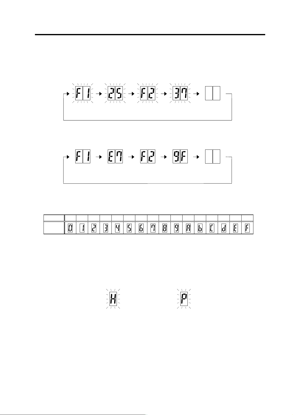
The axis No. and alarm/warning No. alternate on the display. The display flickers when an alarm
occurs.
Numbers displayed on LED
No. 0 1 2 3 4 5 6 7 8 9 A B C D E F
LED
display
(2) Power supply unit
The alarm/warning No. is converted into a symbol and displayed. Refer to section "6-2-1 List of
alarms” and "6-2-2 List of warnings" for details. The display flickers when an alarm or a warning
occurs.
Alarm 71 (flicker)
LED display
during power supply alarm
Warning E9 (flicker)
LED display
during power supply warning
LED displa
y
durin
g
servo alarm or spindle alarm
F1 (flicker)
F+axis No.
25 (flicker)
Alarm No.
Not lit F2 (flicker)
F+axis No.
37 (flicker)
Alarm No.
F1
F+axis No.
E7
Warning No.
Not lit F2
F+axis No.
9F
Warning No.
LED display during servo warning or spindle warning
6. Troubleshooting
6 - 4
6-2 Protective functions list of units
6-2-1 List of alarms
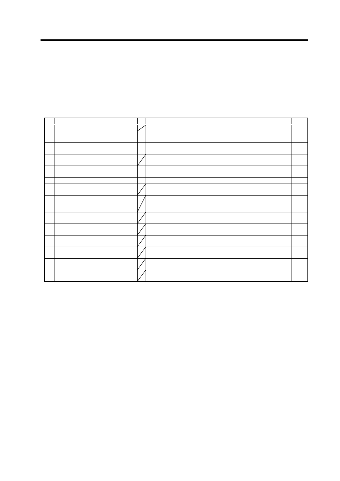
When an alarm occurs, the servo drive unit will make the motor stop by the deceleration control or
dynamic brake. The spindle drive unit will coast to a stop or will decelerate to a stop. At the same time,
the alarm No. will appear on the NC monitor screen and with the LEDs on the front of the drive unit.
Check the alarm No., and remove the cause of the ala rm by followin g this list.
Drive unit alarm
No. Alar m name SV SP Alarm details Reset
11 Axis selection error
The axis No. selection switch setting is incorrect. AR
12 Memory error 1
A CPU or internal memory error was detected during the self-check at
power ON.
AR
13 Software processing error 1
§ §
The software process was not completed within the specified time.
(CPU1)
PR
14 Software processing error 2
{
The software process was not completed within the specified time.
(CPU2)
PR
16 Magnetic pole position detection
error
Creation of the initial magnetic pole, required for motor control, was not
completed.
PR
17 A/D converter error
An error was detected in the A/D converter for current FB detection. PR
18 Motor side detector, initial
communication error
Initial communication with the motor end detector was not possible. PR
19 Synchronous control/detector
communication error
§
Initial communication with the master axis motor end detector was not
possible when the closed current command synchronous control was
set. Or, the communication was cut off.
PR
1A Machine side detector, initial
communication error
Initial communication with the linear scale or ball screw end detector
was not possible.
PR
1B Machine side detector, CPU error 1
A CPU initial error was detected with the linear scale or ball screw end
detector.
PR
1C Machine side detector,
EEPROM/LED abnormality
§
An error was detected in the data stored in the memory with the linear
scale. Or, LED deterioration was detected with the linear scale.
PR
1D Machine side detector, data error
§
A data error was detected with the linear scale or ball screw end
detector.
PR
1E Machine side detector, memory
error
§
An internal memory error was detected with the linear scale. PR
1F Machine side detector,
communication error
§
An error was detected in the communication data with the linear scale
or ball screw end detector. Or, the communication was cut off.
PR
(Note 1) Motor stopping method applied when self-axis dr ive unit alarm occurs is indicated in SV for servo and in SP for spindle.
(Note 2) Servo (SV) alarm stopping method
{: Deceleration control (when SV048, SV055 or SV056 is set)
§: Dynamic brake stop
: Initial error (while motor is stopped)
(Note 3) Spindle (SP) alarm stopping method
{: Deceleration control (when SP038/bit0=1 is set)
§: Coast to a stop
: Initial error (while motor is stopped)
Resetting methods
NR : Reset with the NC RESET button. This alarm can also be reset with the PR and AR resetting conditions.
PR : Reset by turning the NC power ON again. This alarm can also be reset with the AR resetting conditions.
When the control axis is removed, this alarm can be reset with the NC RESET button. (Excluding alarms 32 and 37.)
AR : Reset by turning the servo drive unit power ON again.