bnp-b2365(eng)b.pdf - 第38页
1. Installation 1 - 22 1-5 Noise measures Noise includes "propagation noise" generated from the power supply or relay, etc., and propagated along a cable causing the power supply unit or drive unit to malfuncti…

1. Installation
1 - 21
[8] With the sensor installation seat's R section butted against the notched fitting section, fix the
sensor installation seat with a mounting screw (M5 x 0.8 screws). A locking agent should be
applied on the mounting screw before it is tightened.
[9] When using the specifications (TS1860N2770,
TS1860N2776, TS1860N2183, TS1860N2187) with
installation plate (ring) for the sensor section,
provide a notched fitting section on the machine side
as shown on the right, and fit the sensor installation
plate's ø108H5 here. The gap does not need to be
adjusted when using the installation plate.
[10] Make sure that force is not constantly applied on the
sensor's lead wires.
(3) Installing the PCB section
[1] Install the PCB where it will not be subject to water or oil, etc.
[2] Drill two ø11mm or smaller installation seats, and fix the PCB with pan head screws (M5 × 0.8
screws).
[3] Provide a space of 25mm from the installation surface to treat the lead wires for the intermediate
connector.
[4] Select the minimum required length for the lead wires from the sensor to the intermediate
connector, and wire them as far away from other power wires as possible.
[5] Make sure that force is not constantly applied on the PCB lead wire connections.
[6] The check pins on the PCB could break if excessive force is applied.
Installing the sensor with
Installation plate (ring)
ø 108
-0.005
-0.020
[
Unit: mm
]
3.5mm or less
Butt the R section of the sensor installation seat
a
g
ainst here
Butt the back side of the sensor installation
seat against here
Notched section's
outer diameter
2-M5
×
0.8 screw
Notched section's
outer diameter
29mm
Outline
drawing
designated
dimensions
Shape of notched fitting section
1. Installation
1 - 22
1-5 Noise measures
Noise includes "propagation noise" generated from the power supply or relay, etc., and propagated
along a cable causing the power supply unit or drive unit to malfunction, and "radiated noise"
propagated through air from a peripheral device, etc., and causing the power supply unit or drive unit to
malfunction.
Always implement these noise measures to prevent the peripheral devices and unit from malfunctioning.
The measures differ according to the noise propagation path, so refer to the following explanation and
take appropriate measures.
(1) General noise measures
• Avoid laying the drive unit's power line and signal wire in a parallel or bundled state. Always
separate these wires. Use a twisted pair shielded wire for the detector cable and signal wires
such as the communication cable connected with the NC, and accurately ground the devices.
• Use one-point grounding for the drive unit and motor.
• Accurately ground the AC reactor.
(2) Propagation noise measures
Take the following measures when noise generating devices are installed and the power supply
unit or drive unit could malfunction.
• Install a surge killer on devices (magnetic contacts, relays, etc.) which generate high levels of
noise.
• Install a power line filter in the stage before the power supply unit.
• Install a ferrite core on the signal wire.
• Ground the shield of the servo detector's cable with a cable clamp.
• Wire the spindle PLG detector cable away from other wires.
(3) Measures against radiated noise
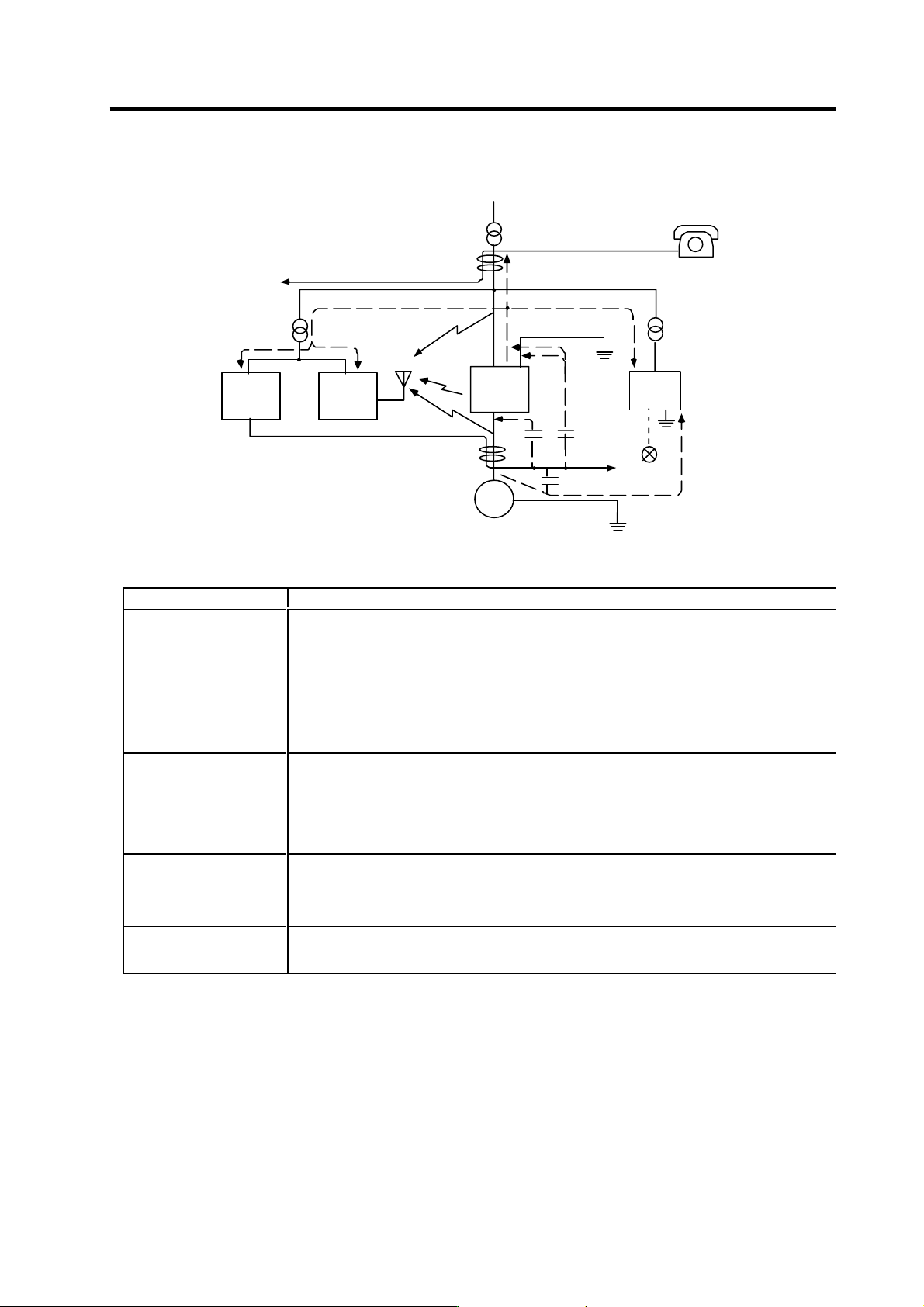
The types of propagation paths of the noise and the noise measures for each propagation path are
shown below.
Noise generated from
drive unit
Noise directly radiated
from drive unit
Airborne
propagation noise
Path [1]
Noise radiated from
power line
Magnetic induction
noise
Path [2]
Path [4]
and [5]
Noise radiated from
servomotor/spindle motor
Static induction
noise
Path [3]Path [6]
Noise propagated over
power line
Cable propagation
noise
Path [7]
Noise lead in from
grounding wire by
leakage current
Path [8]
1. Installation
1 - 23
[1]
[2]
[3]
[4]
[5]
[6]
[7]
[8]
Drive
unit
Sensor
Servomotor
S pindle motor
M
Receiver
Instru-
ment
[2]
[7]
Sensor
power
supply
Generated noise of drive system
Noise propagation path Measures
[1] [2] [3]
When devices such as instrument, receiver or sensor, which handle minute signals and are easily
affected by noise, or the signal wire of these devices, are stored in the same panel as the drive
units and the wiring is close, the device could malfunction due to airborne propagation of the noise.
In this case, take the following measures.
(a) Install devices easily affected as far away from the drive units as possible.
(b) Lay devices easily affected as far away from the signal wire of the drive unit as possible.
(c) Avoid laying the signal wire and power line in a parallel or bundled state.
(d) Insert a line noise filter on the input/output wire or a radio filter on the input to suppress the
noise radiated from the wires.
(e) Use a shield wire for the signal wire and power line, or place in separate metal ducts.
[4] [5] [6]
If the signal w ire is laid in parallel to the pow er line, or if it is bundled with the pow er line, the noise
could be propagated to the signal wire and cause malfunction because of the magnetic induction
noise or static induction noise. In this case, take the following measures.
(a) Install devices easily affected as far away from the drive unit as possible.
(b) Lay devices easily affected as far away from the signal wire of the drive unit as possible.
(c) Avoid laying the signal wire and power line in a parallel or bundled state.
(d) Use a shield wire for the signal wire and power line, or place in separate metal ducts.
[7]
If the power supply for the peripheral devices is connected to the power supply in the same system
as the drive units, the noise generated from the power supply unit could back flow over the power
line and cause the devices to malfunction. In this case, take the following measures.
(a) Install a radio filter on the power supply unit's power line.
(b) Install a power filter on the power supply unit's power line.
[8]
If a closed loop is created by the peripheral device and drive unit's grounding wire, a leakage
current could flow and cause the device to malfunction.
In this case, change the device grounding methods and the grounding place.