bnp-b2365(eng)b.pdf - 第297页
5. Spindle Adjustment 5 - 52 (4) Adjusting the parameter s Adjust the following parameters while measuri ng the synchronous error betwe en the servo and spindle. The servo axis speed loop gain is valid fo r all control, …
5. Spindle Adjustment
5 - 51
(2) Adjusting the acceleration/decelera tion time constant
Synchronous tap synchronizes the operation with the servo. Generally, the spindle takes longer to
accelerate and decelerate, so the acceleration/deceleration time constant is determined on the
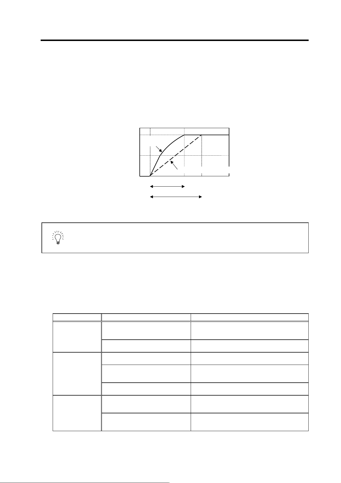
spindle side. Measure the acceleration time for the S command, and set a value 1.5-fold that as
the standard value.
If the spindle maximum rotation speed is 2000r/min during synchronous tap operation, first carry
out 2000r/min acceleration/deceleration with the S command as shown below. Then, measure the
total acceleration/deceleration time in a linear, 2-step or 3-step state. The time constant for
synchronous tap operation is 450ms which is 1.5-fold 300m s.
Measuring the acceleration time during S command
POINT
When carrying out synchronous tap operation with a motor capabl e of coil
changeover, either the high-speed coil or low-speed coil is used. Fix the coil
being used, and measure the acceleration time by issuing the S command in
this case.
(3) Synchronous tap trial operation
Carry out trial operation after setting the parameters. Carry out dry operation without tapping or a
workpiece, and confirm the amount that the spindle moves in respect to the servo axis. If an alarm
occurs when there is no load, check the cause with the following table.
Troubleshooting for synchronous tap trial operation
Fault Cause Remedy
Excessive error
alarm occurs
(ALM52)
The synchronous tap detector direction is
set in reverse.
Check the SP193/bit5 setting.
0 = Forward run, 1 = Reverse run
The motor cannot follow because the tap
time constant is too short.
Readjust the tap time constant.
Set a value double the value for the S command.
Overcurrent alarm
occurs (ALM32)
The motor cannot follow because the tap
time constant is too short.
Readjust the tap time constant.
Set a value double the value for the S command.
The speed loop gain is too high for
synchronous tap control (Is there vibration
when changing to synchronous control?)
The SP194 setting value is too large.
Set 100% as the standard.
The current loop gain is too high during
synchronous tap control.
The SP219, SP220 setting value is too large.
Set 100% as the standard.
The closed loop and semi-closed loop
settings for spindle control are incorrect.
Check which detector's FB is being used.
Spindle ENC = full closed loop: SP193/bit0 =0
Motor PLG = semi-closed loop: SP193/bit0 =1
The spindle rotation
movement amount
does not match the
command
The gear ratio setting is incorrect. Check the machine gear ratio.
Number of gear teeth on spindle side : SP025 to SP028
Number of gear teeth on motor side : SP029 to SP032
0
1000
2000
Acceleration time durin
g
S command
Standard acceleration time during synchronous tap (1.5-fold)
Speed FB
[r/min]
0 300 450 [ms]
During S
command
During synchronous tap control
5. Spindle Adjustment
5 - 52
(4) Adjusting the parameters
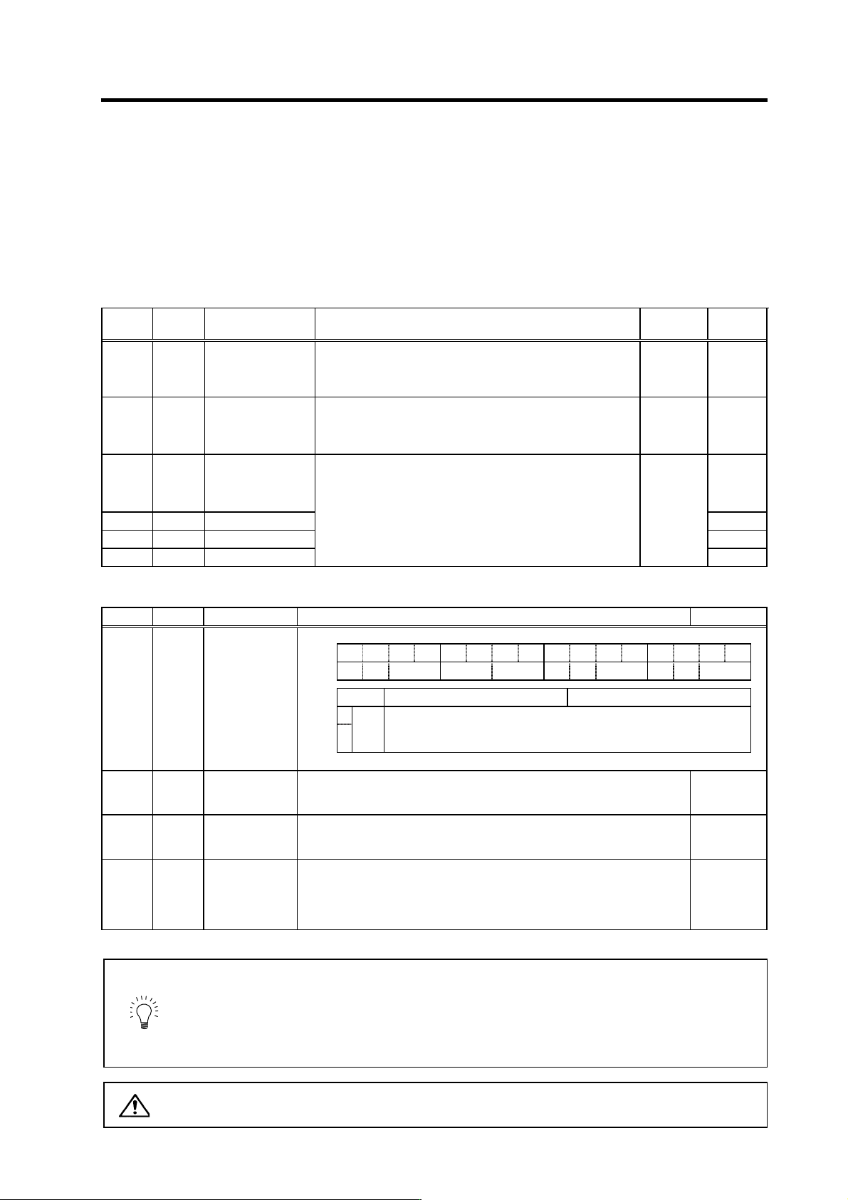
Adjust the following parameters while measuring the synchronous error between the servo and
spindle. The servo axis speed loop gain is valid for all control, so adjust the speed loop gain only
on the spindle side. Adjust mainly the lost motion compensation parameters on the servo side.
When these have already been adjusted when measuring the roundness, etc., they do not need to
be adjusted again. If the acceleration/deceleration is delayed for one of the axes, set the
acceleration feed forward gain for the delayed axis to compensate the synchronous delay.
Spindle adjustment parameters
No. Abbr. Parameter name Details
Setting
range
Standard
SP194 VGTP* Synchronized
tapping control
speed loop gain
proportional term
Set the speed loop proportional gain in synchronized tapping
mode.
0 to 1000 63
SP195 VGTI* Synchronized
tapping control
speed loop gain
integral term
Set the speed loop integral gain in synchronized tapping mode.
0 to 1000 60
SP200 FFCI* Synchronized
tapping control
acceleration feed
forward gain (gear 1)
0
SP201 FFC2* (Gear 2) 0
SP202 FFC3* (Gear 3) 0
SP203 FFC4* (Gear 4)
Set the acceleration feed forward gain for selection of gear 000
during synchronized tapping.
This parameter should be used when an error of relative
position to Z-axis servo is large.
0 to 1000
(%)
0
Spindle adjustment parameters
No. Abbr. Parameter name Details Setting range
FEDCBA98765 4 3 2 10
aflt zrn2 afse ovs lmc omr zrn3 vfct upc vcnt
bit Meaning when set to 0 Meaning when set to 1
8
Set the compensation amount with SV016 (LMC1) and SV041 (LMC2).
9
lmc
00: Lost motion compensation stop
01: Lost motion compensation ty pe 1
10: Lost motion compensation ty pe 2
11: Setting prohibited
SV027 SSF1 Servo function
selection 1
SV016 LMC1 Lost motion
compensation 1
Set the compensation amount based on the stall (rated) current of the motor.
The standard setting is double of the friction torque. Setting to "0" means the
compensation amount is zero.
-1 to 200
(Stall [rated]
current %)
SV041 LMC2 Lost motion
compensation 2
Set this with SV016 (LMC1) only when you wish to set the lost motion
compensation amount to be different depending on the command directions.
Normally, set to "0".
-1 to 200
(Stall [rated]
current %)
SV015 FFC Acceleration rate
feed forward gain
When a relative error in the synchronous control is large, apply this parameter
to the axis that is delaying. The standard setting value is "0". For the SHG
control, set to "100".
To adjust a relative error in acceleration/deceleration, increase the value by
50 to 100 at a time.
0 to 999
(%)
POINT
1. Stop the machine error compensation function (backlash comp ensation,
pitch error compensation, etc.) when measuring the synchronous error.
2. The servo's speed loop gain has an effect on all control, so do not adjust it
for synchronous tap. The spindle parameters are dedicated for synchronous
tap control, so improve the synchronization accuracy by adju sting the spindle
parameters when possible.
CAUTION
The above spindle parameters adjusted when adjusting the synchronou s tap
are all validated when the NC p ower is turned ON again.

5. Spindle Adjustment
5 - 53
(5) Synchronous tap cutting operation
After adjusting the parameters, mount the tap and workpiece, and carry out actual cutting. Various
elements affect the tap cutting. Even if the synchronous accuracy (electrical accuracy) is good up
to this point, it may not enable cutting with a sufficient accuracy. Check the items in the following
table and improve the cutting accuracy.
Investigation items for improving cutting accuracy
Investigation item Remedy
Use a spiral tape (recommended) with good cutting chip discharge
performance
1. The cutting chip discharge is poor (cutting
chips get caught)
Adjust the cutting speed to an appropriate value
2. The tap cutting performance is poor Replace the tap
3. The tap hole diameter is too large Set the tap hole diameter to an appropriate size
4. The spindle PLG waveform adjustment is
insufficient
Readjust the offset and gain
5. The servo axis backlash compensation
amount is incorrect
Adjust the backlash compensation amount
6. The servo axis pitch error compensation
amount is incorrect
Adjust the pitch error compensation amount
7. The acceleration/deceleration time constant is
short
Increase the acceleration/deceleration time constant to improve the
accuracy
8. The tap depth is too deep for the tap diameter Set the tap depth to up to 3-times the tap diameter
9. The spindle center deviates Check the tap mounting state
10. The spindle backlash is too large Improve the machine side
11. The spindle load inertia is too large (3-times or
more)
Try using fixed position loop excitation (SP193/bit3 = 1)
Note that vibration noise will be generated easily
12. The cutting load is large (50% or more)
The tap hole is too small → Check the tap mounting state
The spindle center deviates → Check the tap mounting state
The tap cutting performance is poor → Replace the tap
Try using fixed position loop excitation (SP193/bit3 = 1)
If the tap breaks, investigate the following items.
Investigation items when tap breaks
Investigation item Remedy
1. The program's screw pitch and tap pitch do not
match.
Set the program to the tap.
2. The tap center deviation is large Check the accuracy of the spindle and the tap mounting state
3. The tap hole is too shallow Drill the tap hole to an appropriate depth
4. The tap hole is too small Drill the tap hole to an appropriate size