bnp-b2365(eng)b.pdf - 第24页
1. Installation 1 - 8 1-2 Installation of spindle motor CAUTION 1. Do not hold the cables, axis or detec tor when transporting the motor. Failure to observe this could lead to faults or injuries. 2. Securely fix the moto…
1. Installation
1 - 7
1-1-7 Cable stress
[1] Sufficiently consider the cable clamping method so that bending stress and the stress from the
cable's own weight is not applied on the cable connection part.
[2] In applications where the servomotor moves, make sure that excessive stress is not applied on the
cable.
If the detector cable and servomotor wiring are stored in a cable bear and the servomotor moves,
make sure that the cable bending part is within the range of the optional detector cable.
Fix the detector cable and power cable enclosed with the servomotor.
[3] Make sure that the cable sheathes will not be cut by sharp cutting chips, worn by contacting the
machine corners, or stepped on by workers or vehicles.
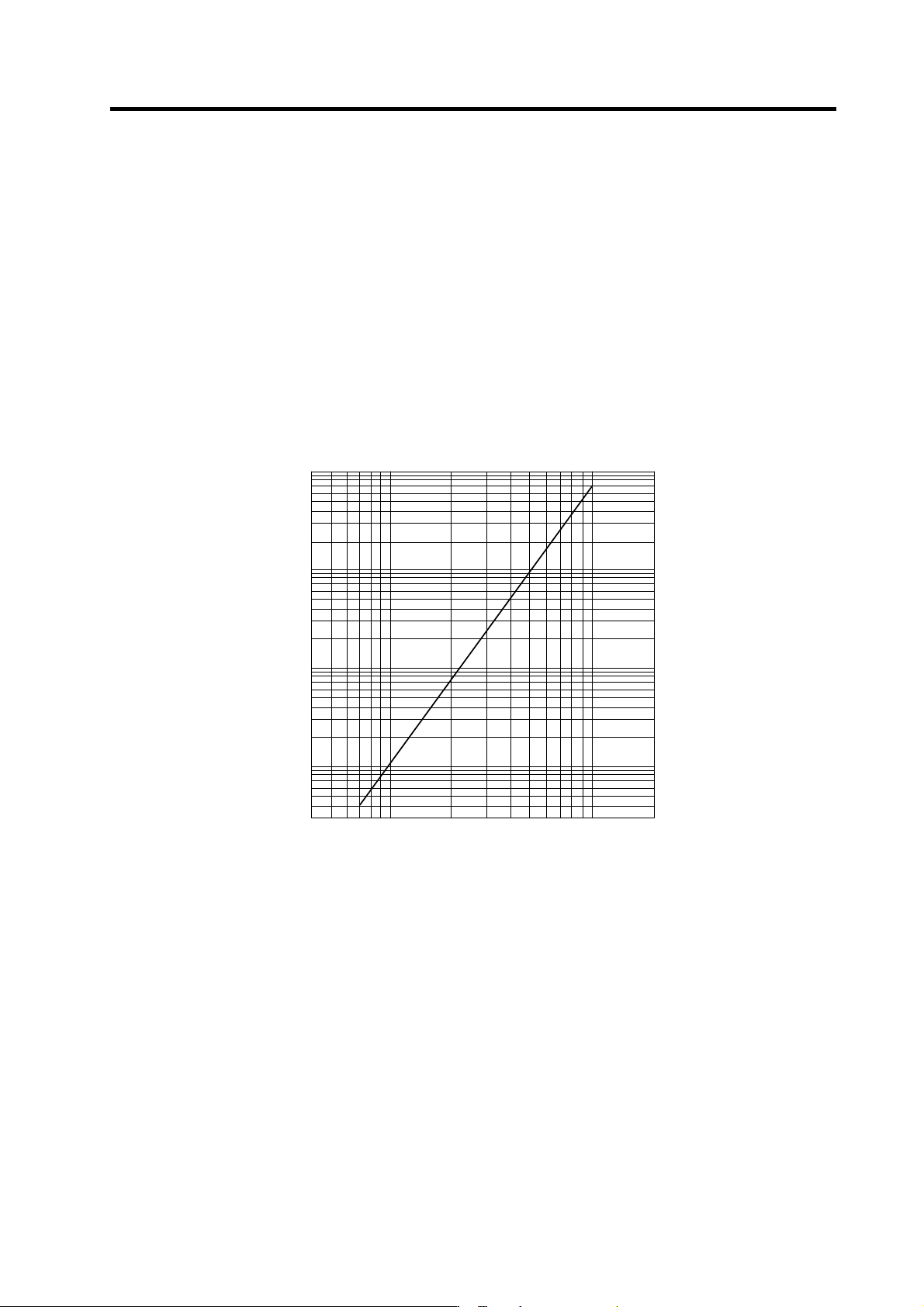
The bending life of the detector cable is as shown below. Regard this with a slight allowance. If the
servomotor/spindle motor is installed on a machine that moves, make the bending radius as large as
possible.
4 7 10 20 40 70 100 200
1×10
8
5×10
7
2×10
7
1×10
7
5×10
6
2×10
6
1×10
6
5×10
5
2×10
5
1×10
5
5×10
4
3×10
4
Detector cable bending life
(Material of Mits ubishi optional detector cable: A14B2343)
(Note)
The values in this graph are calculat ed values and are not guaranteed.
Bending radius (mm )
No. of bends (times)
4 7 10 20 40 70 100 200
3 x 10
4
5 x 10
4
1 x 10
5
2 x 10
5
5 x 10
5
1 x 10
6
2 x 10
6
5 x 10
6
1 x 10
7
2 x 10
7
5 x 10
7
1 x 10
8
1. Installation
1 - 8
1-2 Installation of spindle motor
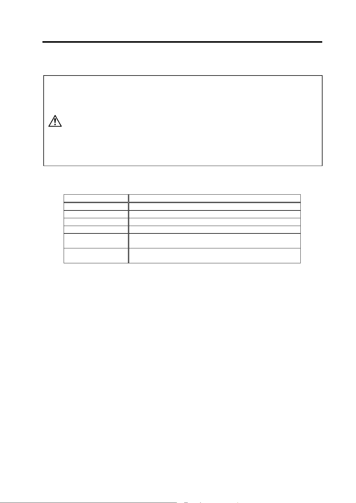
CAUTION
1. Do not hold the cables, axis or detector when transporting the motor. Failure to
observe this could lead to faults or injuries.
2. Securely fix the motor to the machine. Insufficient fixing could lead to the
motor deviating during operation. Failure to observe this could lead to
injuries.
3. When coupling to a servomotor shaft end, do not apply an impact by
hammering, etc. The detector could be damaged.
4. Never touch the rotary sections of the motor during operations. Install a
cover, etc., on the shaft.
5. Do not apply a load exceeding the tolerable load onto the servomotor shaft.
The shaft could break. Failure to observe this could lead to injuries.
6. Do not connect or disconnect any of the connectors while the power is ON.
1-2-1 Environmental conditions
Environment Conditions
Ambient temperature 0°C to +40°C (with no freezing)
Ambient humidity 90%RH or less (with no dew condensation)
Storage temperature -20°C to +65°C (with no freezing)
Storage humidity 90%RH or less (with no dew condensation)
At mosphere
Indoors (Where unit is not subject to direct sunlight)
No corrosive gases, flammable gases, oil mist or dust
Altitude
Operation/storage: 1000m or less above sea level
Transportation: 10000m or less above sea level
(Note) Refer to each spindle motor specifications for details on the spindle motor vibration
conditions.
1. Installation
1 - 9
1-2-2 Shaft characteristics
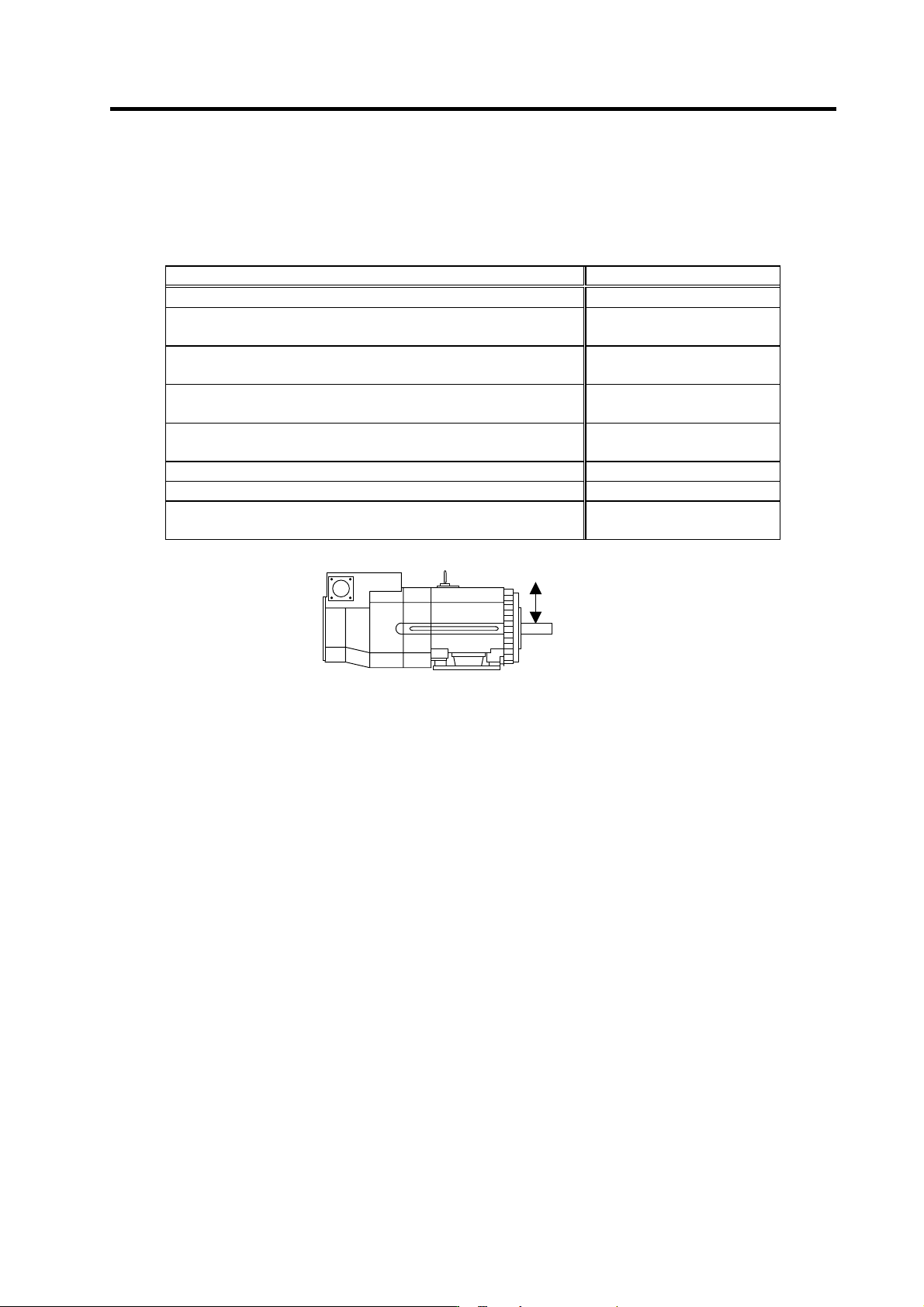
There is a limit to the load that can be applied on the motor shaft. Make sure that the load applied on the
radial direction, when mounted on the machine, is below the tolerable values given below. These loads
also affect the motor output torque, so consider them when designing the machine.
Spindle motor Tolerable radial load
SJ-V3.7-02ZM 490 N
SJ-V2.2-01, SJ-V3.7-01
SJ-V7.5-03ZM, SJ-V11-06ZM
980 N
SJ-V5.5-01, SJ-V11-08ZM
SJ-PMF01830-00
1470 N
SJ-V7.5-01, SJ-V11-01
SJ-V22-06ZM, SJ-V30-02ZM, SJ-PMF03530-00
1960 N
SJ-V11-09, SJ-V15-01, SJ-V15-03, SJ-V18.5-01, SJ-V18.5-03
SJ-V22-01, SJ-V22-05, SJ-V26-01, SJ-30A
2940 N
SJ-22XW5 3920 N
SJ-37BP 4900 N
SJ-22XW8, SJ-45BP
SJ-V55-01
5880 N
(Note) The load point is at the one-half of the shaft length.
Radial load