bnp-b2365(eng)b.pdf - 第27页
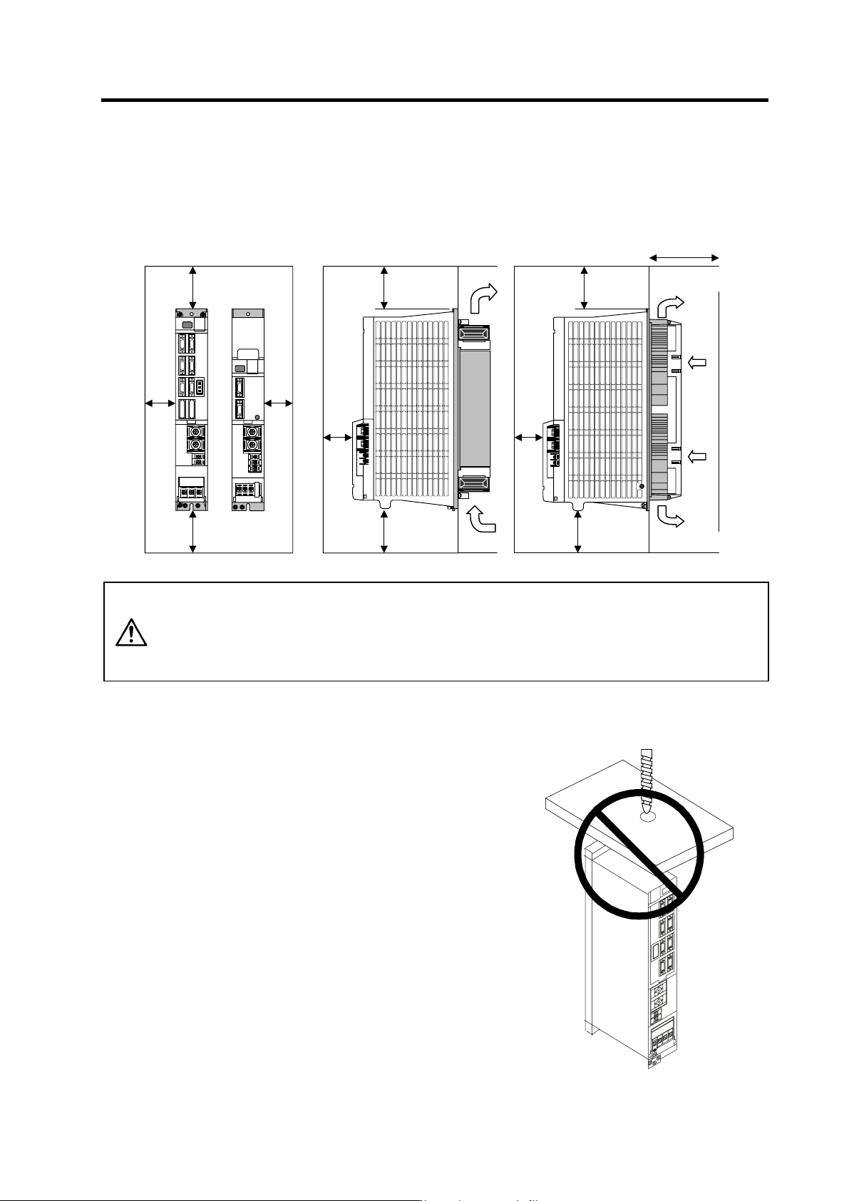
1. Installation 1 - 11 1-3-2 Installation direction and clearance Wire each unit in consideration of the maintainability and the heat dissipation, as well as secure sufficient space for ventilation. 100mm o r more 100mm …
1. Installation
1 - 10
1-3 Installation of the control unit
CAUTION
1. Install the unit on noncombustible material. Direct installation on
combustible material or near combustible materials may lead to fires.
2. Follow the instructions in this manual and install the unit while allowing for
the unit weight.
3. Do not get on top of the units or motor, or place heavy objects on the unit.
Failure to observe this could lead to injuries.
4. Always use the unit within the designated environment conditions.
5. Do not let conductive objects such as screws or metal chips, etc., or
combustible materials such as oil enter the units.
6. Do not block the units intake and outtake ports. Doing so could lead to
failure.
7. The units and servomotor are precision devices, so do not drop them or apply
strong impacts to them.
8. Do not install or run units or servomotor that is damaged or missing parts.
9. When storing for a long time, please contact your dealer.
10. Always observe the installation directions. Failure to observe this could lead to
faults.
11. Secure the specified distance between the units and panel, or between the
units and other devices. Failure to observe this could lead to faults.
1-3-1 Environmental conditions
Environment Conditions
Ambient temperature 0°C to +55°C (with no freezing)
Ambient humidity 90%RH or less (with no dew condensation)
Storage temperature -15°C to +70°C (with no freezing)
Storage humidity 90%RH or less (with no dew condensation)
At mosphere
Indoors (no direct sunlight);
no corrosive gases, inflammable gases, oil mist, dust or conductive particles
Altitude
Operation/storage: 1000m or less above sea level
Transportation: 10000m or less above sea level
Vibration
Operation/storage: 4.9m/s
2
(0.5G) or less
Transportation: 49m / s
2
(5G) or less
(Note) When installing the machine at 1,000m or more above sea level, the heat dissipation
characteristics will drop as the altitude increases. The upper limit of the ambient
temperature drops 1°C with every 100m increase in altitude. (The ambient temperature at
an altitude of 2,000m is between 0 and 45°C.)
1. Installation
1 - 11
1-3-2 Installation direction and clearance
Wire each unit in consideration of the maintainability and the heat dissipation, as well as secure
sufficient space for ventilation.
100mm or
more
100mm or
more
10mm
or
more
100mm or
more
100mm or
more
50mm
or more
100mm or
more
100mm or
more
75mm or more
50mm
or more
10mm
or
more
CAUTION
The ambient temperature condition for the power supply unit or the drive units is
55°C or less. Because heat can easily accumulate in the upper portion of the
units, give sufficient consideration to heat dissipation when designing the panel.
If required, install a fan in the panel to agitate the heat in the upper portion of the
units.
1-3-3 Prevention of entering of foreign matter
Treat the cabinet with the following items.
• Make sure that the cable inlet is dust and oil proof by using
packing, etc.
• Make sure that the external air does not enter inside by
using head radiating holes, etc.
• Close all clearances.
• Securely install door packing.
• If there is a rear cover, always apply packing.
• Oil will tend to accumulate on the top. Take special
measures such as oil-proofing to the top so that oil does
not enter the cabinet from the screw holds.
• After installing each unit, avoid machining in the periphery.
If cutting chips, etc., stick onto the electronic parts, trouble
may occur.
• When using the unit in an area with toxic gases or high
levels of dust, protect the unit with air purging (system to
blow clean air so that the panel's inner pressure is higher
than the outer pressure).
1. Installation
1 - 12
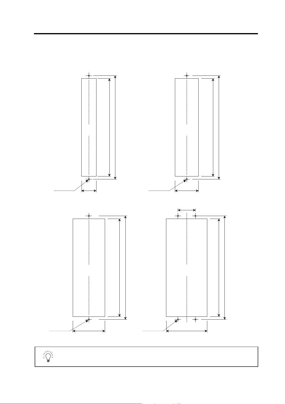
1-3-4 Panel installation hole work drawings (Panel cut drawings)
Prepare a square hole to match the unit width.
[Unit: mm]
Square
hole
(Note 1)
342
360
52
2-M5 screw
342
360
82
2-M5 screw
Square hole
(Note 1)
342
360
112
2-M5 screw
Square hol e
(Note 1)
342
360
142
4-M5 screw
60
Square hol e
(Note 1)
Unit width: 60mm (only with fin)
Unit width: 90mm
Unit width: 120mm Unit width: 150mm
POINT
1. Attach packing around the square hole to provide a seal.
2. A square hole does not need to be machined on the MDS-C1-V1-10 or
smaller, MDS-C1-V2-1010 or smaller and MDS-C1-SP-15 or smaller units.