bnp-b2365(eng)b.pdf - 第204页
4. Servo Adjustment 4 - 5 No. Abbrev . Parameter name Explana tion Setting ran ge SV005 VGN1 Speed loop gain 1 Set the speed loop gain. Set this according to the load inertia size. The higher the setting value is, the mo…
4. Servo Adjustment
4 - 4
4-2 Gain adjustment
4-2-1 Current loop gain
No. Abbrev. Parameter name Explanation Setting range
SV009 IQA Current loop q axis lead
compensation
SV010 IDA Current loop d axis lead
compensation
1 to 20480
SV011 IQG Current loop q axis gain
SV012 IDG Current loop d axis gain
Set the gain of current loop.
As this setting is determined by the motor’s electrical
characteristics, the setting is fixed for each type of motor.
Set the standard values for all the parameters depending on
each motor type.
1 to 8192
4-2-2 Speed loop gain
(1) Setting the speed loop gain
The speed loop gain 1 (SV005: VGN1) is an important parameter for determining the
responsiveness of the servo control. During servo adjustment, the highest extent that this value
can be set to becomes important. The setting value has a large influence on the machine cutting
precision and cycle time.
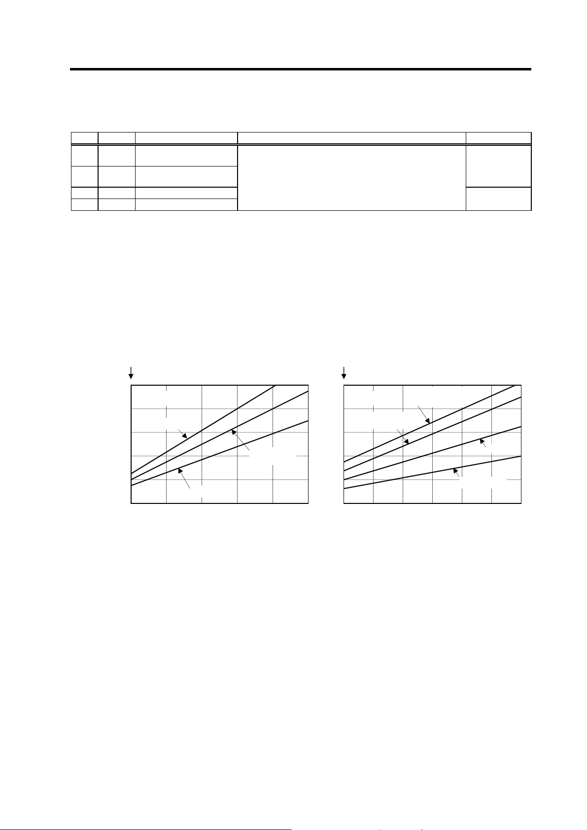
[1] Refer to the following table and set the standard VGN1 according to the size of the entire load
inertia (motor and machine load inertia).
[2] If the standard speed gain setting value is exceeded, the current command fluctuation will
increase even if the speed feedback fluctuates by one pulse. This can cause the machine to
vibrate easily, so set a lower value to increase the machine stability.
<When machine resonance does not occur at the standard VGN1>
Set the standard VGN1. Use the standard value if no problem (such as machine resonance)
occurs. If sufficient cutting precision cannot be obtained at the standard VGN1, VGN1 can be
raised above the standard value as long as a 70 percent margin in respect to the machine
resonance occurrence limit is maintained. The cutting accuracy can also be improved by adjusting
with the disturbance observer.
<When machine resonance occurs at the standard VGN1>
Machine resonance is occurring if the shaft makes abnormal sounds when operating or stopping,
and a fine vibration can be felt when the machine is touched while stopped. Machine resonance
occurs because the servo control responsiveness includes the machine resonance points. (Speed
control resonance points occur, for example, at parts close to the motor such as ball screws.)
Machine resonance can be suppressed by lowering VGN1 and the servo control responsiveness,
but the cutting precision and cycle time are sacrificed. Thus, set a vibration suppression filter and
suppress the machine resonance (Refer to section "4-3-2 Vibration suppression measures"), and
set a value as close as possible to the standard VGN1. If the machine resonance cannot be
sufficiently eliminated even by using a vibration suppression filter, then lower the VGN1.
Load inertia scale (%)
Isolated motor
100
200
0
500
400
300
100 200 400 600300 500
Load inertia scale (%)
Standard
VGN1
Isolated motor
100
200
0
500
400
300
100
200 400 600300 500
HC52~HC152
HC202~HC902
HC53~HC203
<HC>
HC353~HC703
HA40N
HA80N/100N/900N
HA43N~HA103N
<HAN>
HA053~HA33N
HA200N~HA700N
HA203N~HA703N
High-gain specifications High-gain specifications
4. Servo Adjustment
4 - 5
No. Abbrev. Parameter name Explanation Setting range
SV005 VGN1 Speed loop gain 1
Set the speed loop gain.
Set this according to the load inertia size.
The higher the setting value is, the more accurate the control will be,
however, vibration tends to occur.
If vibration occurs, adjust by lowering by 20 to 30%.
1 to 999
POINT
The final VGN1 setting value is 70 to 80% of the maximum value at which the
machine does not resonate.
Suppressing the resonance with the vibration suppression function and increasing
the VGN1 setting is effective for adjusting the servo later.
(2) Setting the speed loop lead compensation
The speed loop lead compensation (SV008: VIA) determines the characteristics of the speed loop
mainly at low frequency regions. 1364 is set as a standard, and 1900 is set as a standard during
SHG control. The standard value may drop in respect to loads with a large inertia.
When the VGN1 is set lower than the standard value because the load inertia is large or because
machine resonance occurred, the speed loop control band is lowered. If the standard value is set
in the leading compensation in this status, the leading compensation control itself will induce
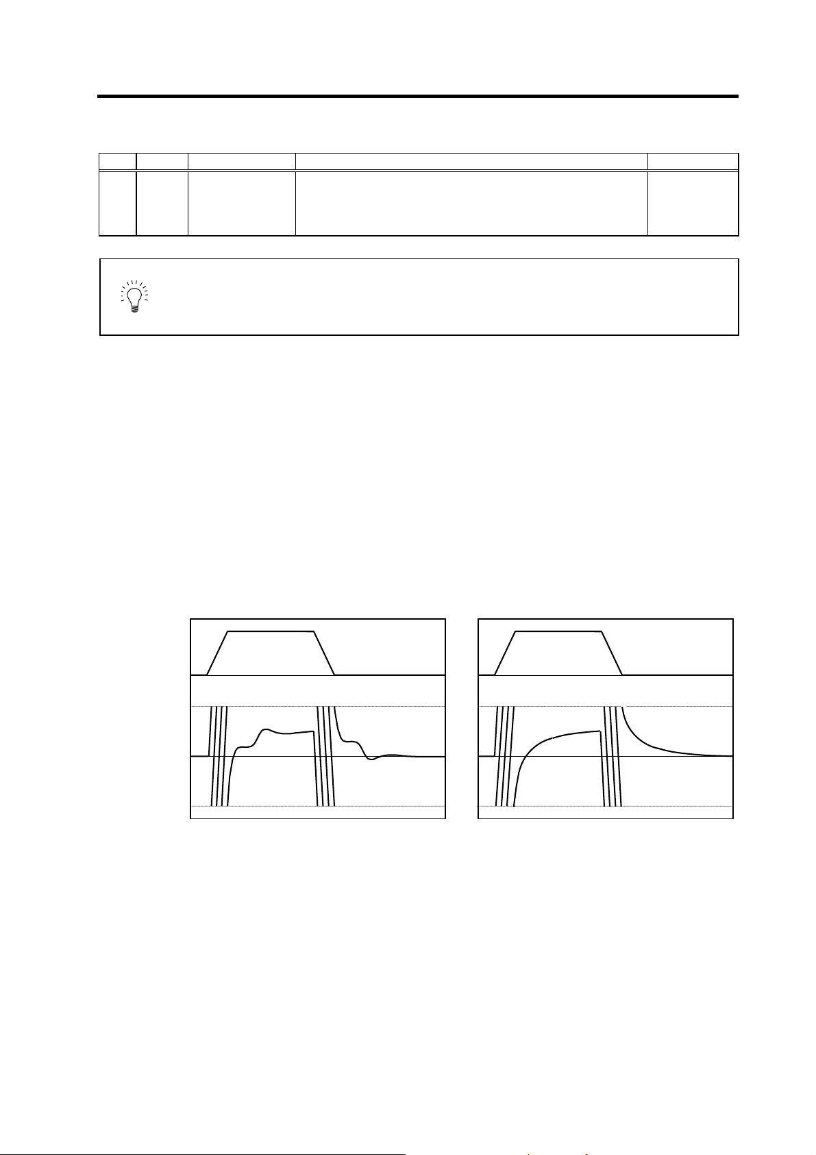
vibration. In concrete terms, a vibration of 10 to 20Hz could be caused during acceleration/
deceleration or stopping, and the position droop waveform could be disturbed when accelerating to
a constant speed and when stopped. (Refer to lower left drawing)
This vibration cannot be suppressed by the vibration suppression functions. Lower the VIA in
increments of 100 from the standard setting value. Set a value where vibration does not occur and
the position droop waveform converges smoothly. Because lowering the VIA causes a drop in the
position control's trackability, the vibration suppression is improved even when a disturbance
observer is used without lowering the VIA. (Be careful of machine resonance occurrence at this
time.)
If VIA is lowered, the position droop waveform becomes smooth and overshooting does not occur.
However, because the trackability in respect to the position commands becomes worse, the
positioning time and accuracy are sacrificed. VIA must be kept high (set the standard value) to
guarantee precision, especially in high-speed contour cutting (generally F = 1000 or higher). In other
words, in a machine aiming for high speed and high accuracy, a large enough value must be set in
VGN1 so that VIA does not need to be lowered. When adjusting, the cutting precision will be better if
adjustment is carried out to a degree where overshooting does not occur and a high VIA is
maintained, without pursuing position droop smoothness.
Vibration waveform with lead compensation control Adjusted position droop waveform
0
0
Speed FB
Position
droop
0
0
Time
D/A output range
Time
Time
Time
4. Servo Adjustment
4 - 6
If there are no vibration or overshooting problems, the high-speed contour cutting precision can be
further improved by setting the VIA higher than the standard value. In this case, adjust by raising
the VIA in increments of 100 from the standard value.
Setting a higher VIA improves the trackability regarding position commands in machines for which
cycle time is important, and the time to when the position droop converges on the in-position width
is shortened.
It is easier to adjust the VIA to improve precision and cycle time if a large value (a value near the
standard value) can be set in VGN1, or if VGN1 can be raised equivalently using the disturbance
observer.
No. Abbrev. Parameter name Explanation Setting range
SV008 VIA Speed loop lead
compensation
Set the gain of the speed loop integration control.
The standard setting is "1364". During the SHG control, the standard
setting is "1900". Adjust the value by increasing/decreasing it by about
100 at a time.
Raise this value to improve contour tracking precision in high-speed
cutting. Lower this value when the position droop vibrates (10 to
20Hz).
1 to 9999
POINT
Position droop vibration of 10Hz or less is not leading compensation control
vibration. The position loop gain must be adjusted.
4-2-3 Position loop gain
(1) Setting the position loop gain
The position loop gain 1 (SV003: PGN1) is a parameter that determines the trackability to the
command position. 47 is set as a standard. Set the same position loop gain value between
interpolation axes.
When PGN1 is raised, the trackability will be raised and the settling time will be shortened, but a
speed loop that has a responsiveness that can track the position loop gain with increased
response will be required. If the speed loop responsiveness is insufficient, several Hz of vibration
or overshooting will occur during acceleration/deceleration. Vibration or overshooting will also
occur when VGN1 is smaller than the standard value during VIA adjustment, but the vibration in
the position loop occurs generally 10Hz or less. (The VIA vibration occurs from 10 to 20Hz.) When
the position control includes machine resonance points (Position control machine resonance
points occur at the tool end parts, etc.) because of insufficient machine rigidity, the machine will
vibrate during positioning, etc. In either case, lower PGN1 and adjust so that vibration does not
occur.
If the machine also vibrates due to machine backlash when the motor stops, the vibration can be
suppressed by lowering the PGN1 and smoothly stopping.
If SHG control is used, an equivalently high position loop gain can be maintained while
suppressing these vibrations. To adjust the SHG control, gradually raise the gain from a setting
where 1/2 of a normal control PGN1 where vibration did not occur was set in PGN1. If the PGN1
setting value is more than 1/2 of the normal control PGN1 when SHG control is used, there is an
improvement effect in position control. (Note that for the settling time the improvement effect is at
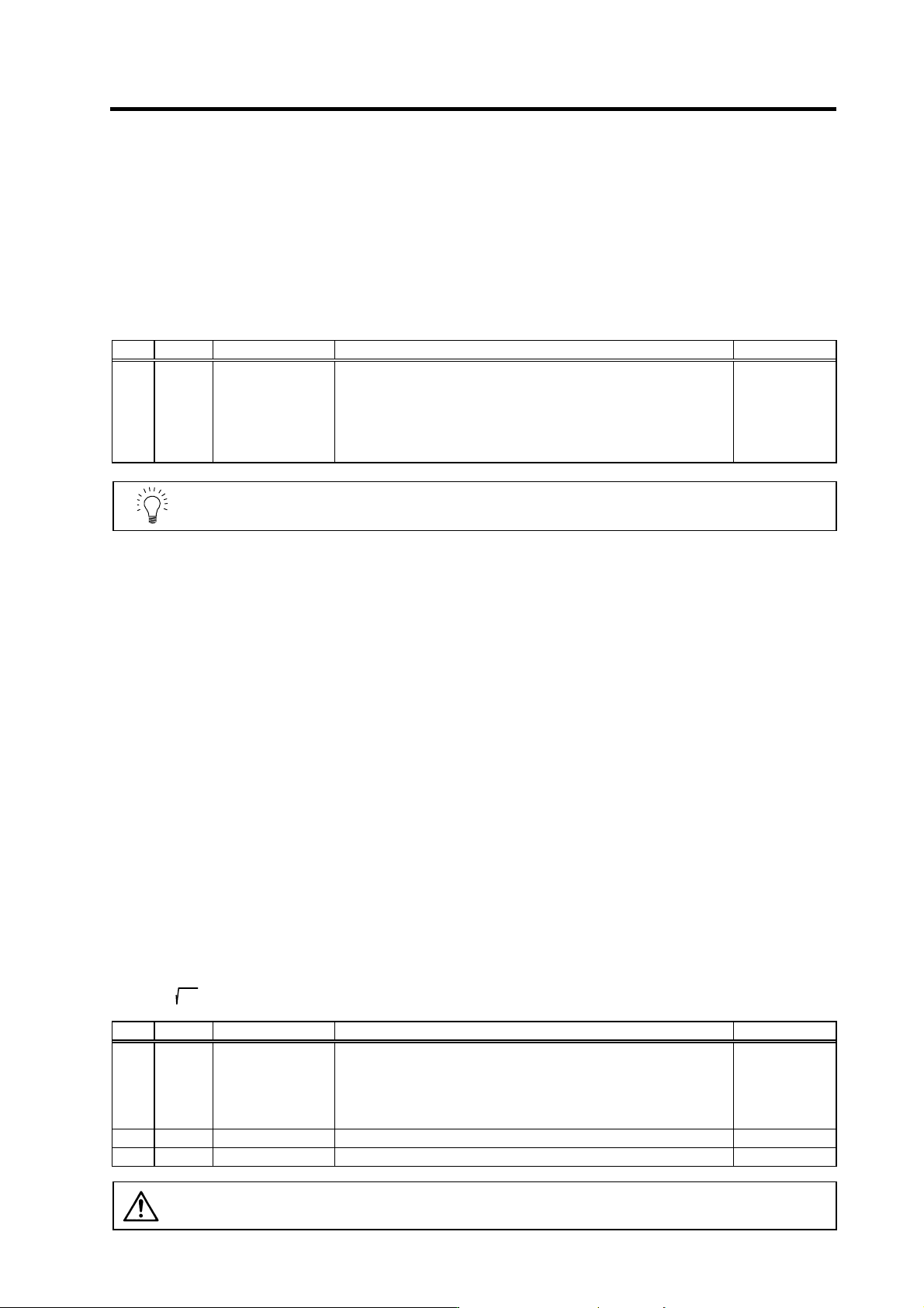
1/
2
or more.)
No. Abbrev. Parameter name Explanation Setting range
SV003 PGN1 Position loop gain 1
Set the position loop gain. The standard setting is "47".
The higher the setting value is, the more precisely the command can be
followed and the shorter the positioning time gets, however, note that a
bigger shock is applied to the machine during acceleration/deceleration.
When using the SHG control, also set SV004 (PGN2) and SV057
(SHGC).
1 to 200
(rad/s)
SV004 PGN2 Position loop gain 2 Set 0. (For SHG control) 0 to 999
SV057 SHGC SHG control gain Set 0. (For SHG control) 0 to 1200
CAUTION
Always set the same value for the position loop gain between the interpolation
axes.