bnp-b2365(eng)b.pdf - 第217页
4. Servo Adjustment 4 - 18 <Measuring the load inertia> If the load inertia is not clear, it can be estimated with the following method. [1] Set the torque of fset (SV032: TOF) fo r the unbalance torque. (Re fer to…
4. Servo Adjustment
4 - 17
(4) Disturbance observer
The disturbance observer can reduce the effect caused by disturbance, frictional resistance or
torsion vibration during cutting by estimating the disturbance torque and compensating it. It also is
effective in suppressing the vibration caused by speed leading compensation control.
<Setting method>
[1] Set SV082/bit7=1.
[2] Adjust VGN1 to the value where vibration does not occur, and then lower it 10 to 20%.
[3] Set the load inertia scale (SV037: JL) with a percentage in respect to the motor inertia of the
total load inertia.
(Refer to next page for measuring the motor shaft conversion load inertia ratio.)
[4] Set the observer filter band (observer pole) in the disturbance observer filter frequency
(SV043: OBS1), and suppress the high frequency disturbance estimate to suppress the
vibration. Set "100" as a standard.
[5] Set the observer gain in disturbance observer gain (SV044: OBS2). The disturbance observer
will function here for the first time. Set 100 first, and if vibration does not occur, increase the
setting by 50 at a time to increase the observer effect.
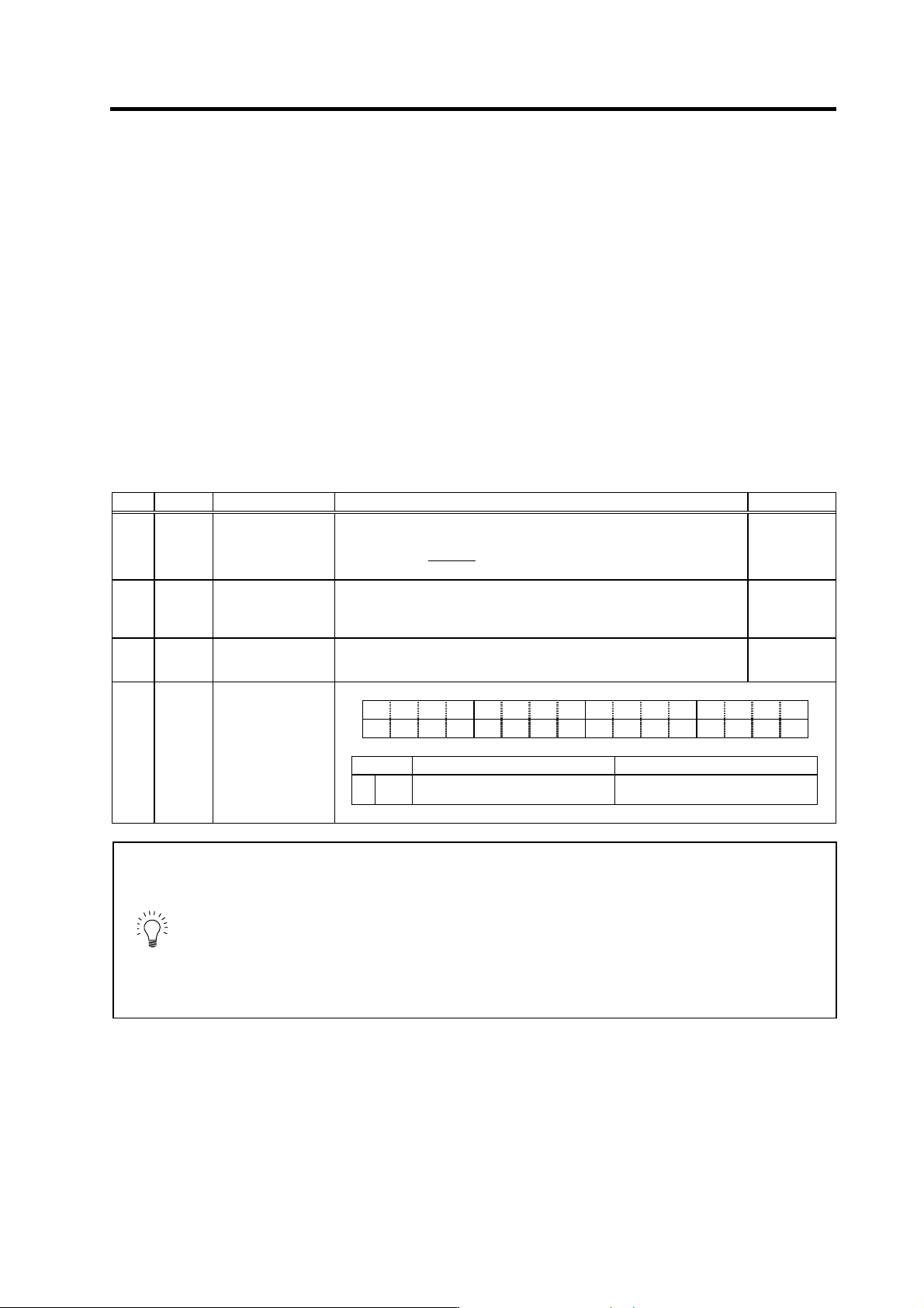
No. Abbrev. Parameter name Explanation Setting range
SV037 JL Load inertia scale Set "the motor inertia + motor axis conversion load inertia" in respect to the
motor inertia.
SV037 (JL) =
Jl + Jm
Jm
× 100
Jm : Motor inertia
Jl : Motor axis conversion load inertia
0 to 5000
(%)
SV043 OBS1
Disturbance
observer filter
frequency
Set the disturbance observer filter band.
Set to "100" as a standard.
To use the disturbance observer, also set SV037 (JL) and SV044 (OBS2).
When not using, set to "0".
0 to 1000
(rad/s)
SV044 OBS2
Disturbance
observer gain
Set the disturbance observer gain. The standard setting is "100" to "300".
To use the disturbance observer, also set SV037 (JL) and SV043 (OBS1).
When not using, set to "0".
0 to 500
(%)
F EDCBA98765 4 3 2 10
obshj lmc3 lmct
bit Meaning when "0" is set Meaning when "1" is set
7
obshj
Normal use Disturbance observer
High-load inertia compatible control
SV082
SSF5 Servo function
selection5
POINT
1. The estimated disturbance torque can be output to the D/A output even if the
disturbance observer gain is zero (OBS2 = 0), and the disturbance observer
is not functioning.
2. Sections where the machine is not moving smoothly can be estimated as
the disturbance.
3. The lost motion compensation must be readjusted when the disturbance
observer is started.
4. SV082/bit7 is the characteristics improvement function when load inertia is
large. SV082/bit7 can be set when load inertia is small, also.
4. Servo Adjustment
4 - 18
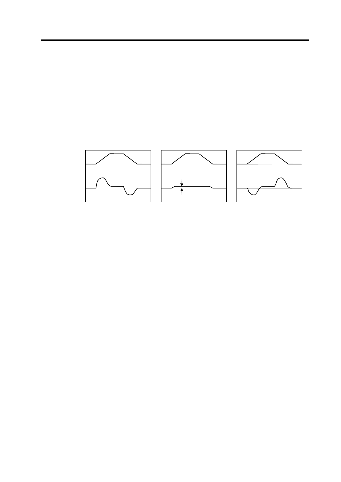
<Measuring the load inertia>
If the load inertia is not clear, it can be estimated with the following method.
[1] Set the torque offset (SV032: TOF) for the unbalance torque. (Refer to "4-3-5 (1) Unbalance
torque and frictional torque".)
[2] Set JL = 100, OBS1 = 600 and OBS2 =0, and reciprocate the axis within the range that it can
be moved smoothly. Set the acceleration/deceleration time constant so that the
acceleration/deceleration torque is larger than the stall (rated) torque (100% or more).
[3] Measure the estimated disturbance torque with the D/A output, and raise JL until the
disturbance torque during acceleration/deceleration is small (until it cannot be observed).
Even if the torque offset is set and JL is an appropriate value, if the axis has a large friction,
the frictional torque will remain in the estimated disturbance torque. Judge the JL setting value,
with frictional torque remaining, as the machine's load inertia scale as shown below.
Speed
command
Estimated
disturbance
torque
0
0
JL: Too small
Time
0
0
JL: Too large
Time
0
0
JL: Appropriate
Time
Frictional
torque
4. Servo Adjustment
4 - 19
4-3-4 Improvement of characteristics during acceleration/deceleration
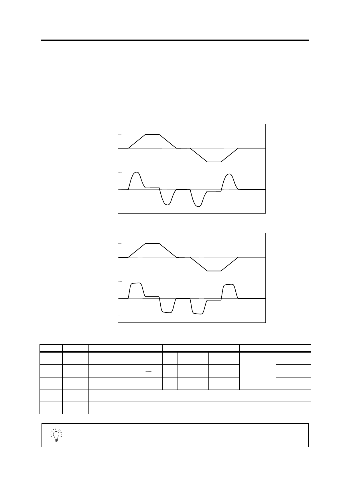
(1) SHG control (option function)
Because SHG control has a smoother response during acceleration/deceleration than
conventional position controls, the acceleration/deceleration torque (current FB) has more ideal
output characteristics (A constant torque is output during acceleration/deceleration.) The peak
torque is kept low by the same acceleration/deceleration time constant, enabling the time constant
to be shortened.
Refer to item "(3) SHG control" in section "4-2-3 Position loop gain" for details on setting SHG
control.
No. Abbrev. Parameter name Setting ratio Setting example Explanation Setting range
SV003
(SV049)
PGN1
(PGN1sp)
Position loop gain 1 1 23 26 33 38 47 1 to 200
SV004
(SV050)
PGN2
(PGN2sp)
Position loop gain 2
8
3
62 70 86 102 125 0 to 999
SV057
(SV058)
SHGC
(SHGCsp)
SHG control gain 6 140 160 187 225 281
Always set with a
combination of
these three
parameters.
0 to 1200
SV008 VIA
Speed loop lead
compensation
Set 1900 as a standard value during SHG control. 1 to 9999
SV015 FFC
Acceleration rate
feed forward gain
Set 100 as a standard value during SHG control. 0 to 999
POINT
SHG control is an option function. If the option is not set in the NC, alarm 37 (at
power ON), or warning E4 and error parameter No. 104 (2304 for M60S/E60
Series NC) will be output.
0
0
3000
200
-200
-3000
0
0
3000
200
-200
-3000
Acceleration/deceleration characteristics during conventional control
Speed command
(r/min)
Current FB
(stall current%)
Time
Time
Acceleration/deceleration characteristics during SHG control
Speed command
(r/min)
Current FB
(stall current %)
Time
Time