bnp-b2365(eng)b.pdf - 第211页
4. Servo Adjustment 4 - 12 (1) Notch filter This servo drive unit mounts 5 not ch filters. Measure the resona nce frequency with the current feedback analog output function, and set that frequency in parameter. However, …
4. Servo Adjustment
4 - 11
4-3-2 Vibration suppression measures
If vibration (machine resonance) occurs, it can be suppressed by lowering the speed loop gain 1
(VGN1). However, cutting precision and cycle time will be sacrificed. (Refer to "4-2-2 Speed loop
gain".) Thus, try to maintain the VGN1 as high as possible, and suppress the vibration using the
vibration suppression functions.
If the VGN1 is lowered and adjusted because vibration cannot be sufficiently suppressed with the
vibration suppression functions, adjust the entire gain (including the position loop gain) again.
<Examples of vibration occurrence>
• A fine vibration is felt when the machine is touched, or a groaning sound is heard.
• Vibration or noise occurs during rapid traverse.
POINT
Suppress the vibration using the vibration suppression functions, and maintain
the speed loop gain (SV005: VGN1) as high as possible.
4. Servo Adjustment
4 - 12
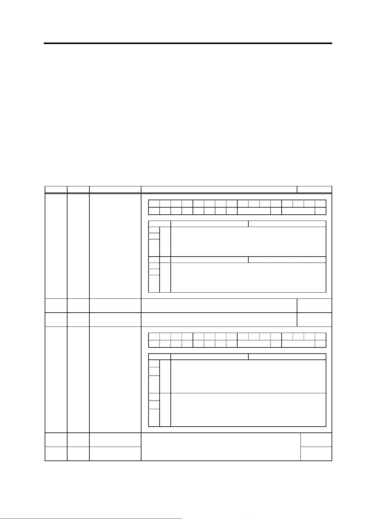
(1) Notch filter
This servo drive unit mounts 5 notch filters. Measure the resonance frequency with the current
feedback analog output function, and set that frequency in parameter.
However, if the notch filter is set to a particularly low frequency, another resonance frequency that
did not vibrate initially may occur. If the notch filter's depth compensation (SV033, nfd1, nfd2) is
adjusted so that the filter does not operate unless necessary, the servo control will be stabilized.
Notch filter 3 is a filter with frequency fixed to 1125Hz, and has no depth compensation.
<Setting method>
[1] Set the resonance frequency in the notch filter frequency (1, 2, 4, 5).
[2] If the machine starts to vibrate at another frequency, raise (make shallower) the notch filter
depth compensation value, and adjust to the optimum value at which the resonance can be
eliminated.
[3] When the vibration cannot be completely eliminated, use also another notch filter for this
frequency.
No. Abbrev. Parameter name Explanation Setting range
FEDCBA98765 4 3 2 10
hvx svx nfd2 nf3 nfd1 zck
bit Meaning when "0" is set Meaning when "1" is set
1 Set the filter depth for Notch filter 1 (SV038).
2 nfd1 Value 000 001 010 011 100 101 110 111
3
Depth (dB)
DeepÅ
Infntly
deep
-18.1 -12.0 -8.5 -6.0 -4.1 -2.5 -1.2
ShallowÆ
4 nf3 Notch filter 3 stop Notch filter 3 start (1125Hz)
5 Set the filter depth of Notch filter 2 (SV046).
6 nfd2 Value 000 001 010 011 100 101 110 111
SV033 SSF2
Servo function
selection 2
7
Depth (dB)
DeepÅ
Infntly
deep
-18.1 -12.0 -8.5 -6.0 -4.1 -2.5 -1.2
ShallowÆ
SV038 FHz1
Notch filter frequency
1
Set the vibration frequency to suppress if machine vibration occurs.
(Valid at 36 or more) When not using, set to "0".
0 to 9000
(Hz)
SV046 FHz2
Notch filter frequency
2
Set the vibration frequency to suppress if machine vibration occurs.
(Valid at 36 or more) When not using, set to "0".
0 to 9000
(Hz)
FEDCBA98765 4 3 2 10
hvx svx nfd2 nf3 nfd1 zck
bit Meaning when "0" is set Meaning when "1" is set
1 Set the filter depth for Notch filter 4 (SV038).
2 nfd4 Value 000 001 010 011 100 101 110 111
3
Depth (dB)
DeepÅ
-
∞
-18.1 -12.0 -8.5 -6.0 -4.1 -2.5 -1.2
ShallowÆ
5 Set the filter depth for Notch filter 5 (SV046).
6 nfd5 Value 000 001 010 011 100 101 110 111
SV083 SSF6
Servo function
selection 6
7
Depth (dB)
DeepÅ
-∞
-18.1 -12.0 -8.5 -6.0 -4.1 -2.5 -1.2
ShallowÆ
SV087 FHz4
Notch filter
frequency 4
0 to 2250
(Hz)
SV088 FHz5
Notch filter
frequency 5
Set the vibration frequency to suppress if machine vibration occurs.
(Valid at 141 or more) When not using, set to "0".
To use this function, set to not "0" (normally "1") when turning the power
ON. This function cannot be used with adaptive filter.
0 to 2250
(Hz)
4. Servo Adjustment
4 - 13
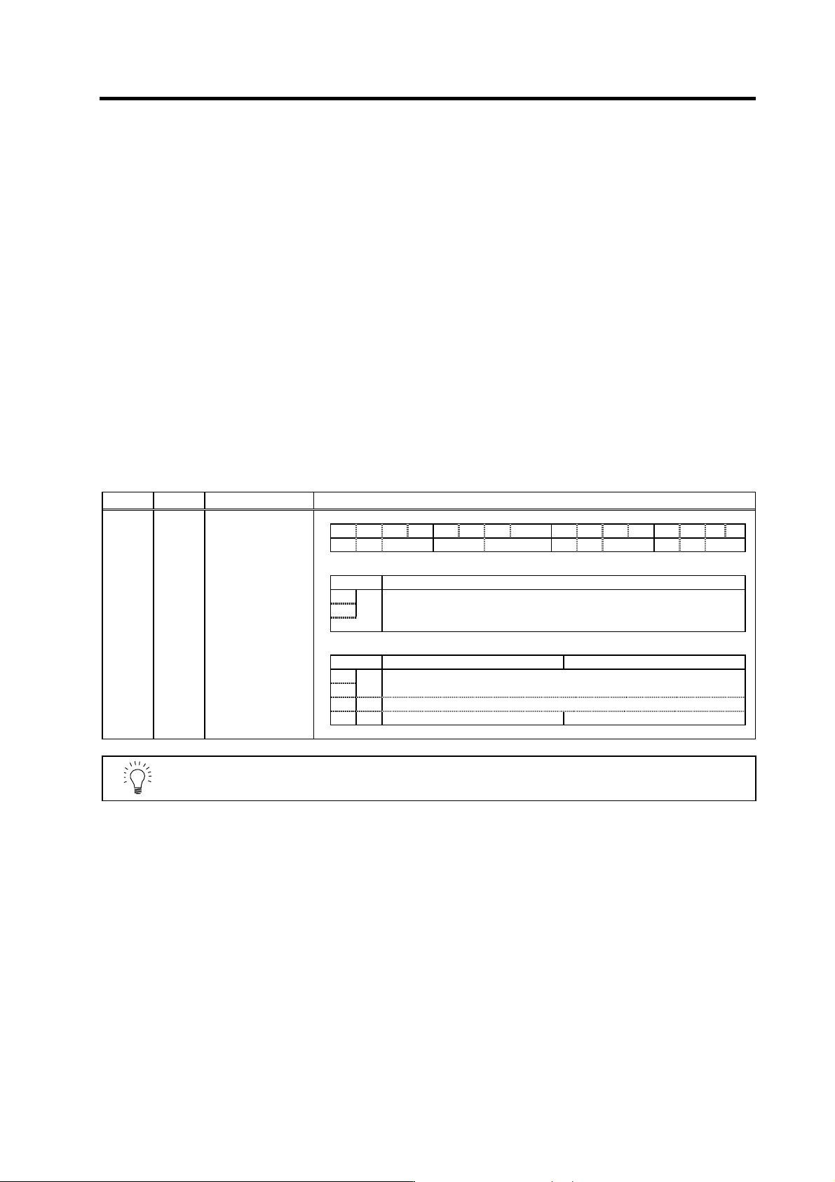
(2) Jitter compensation (Vibration control when motor is stopped.)
The load inertia becomes much smaller than usual if the motor position enters the machine
backlash when the motor is stopped. Because this means that an extremely large VGN1 is set for
the load inertia, vibration may occur.
Jitter compensation can suppress the vibration that occurs at the motor stop by ignoring the
backlash amount of speed feedback pulses when the speed feedback polarity changes.
Increase the number of ignored pulses by one pulse at a time, and set a value at which the
vibration can be suppressed. (Because the position feedback is controlled normally, there is no
worry of positional deviation.)
When jitter compensation is set to an axis that is not vibrating is set, vibration could be induced, so
take care.
(3) Adaptive filter
The servo drive unit detects the machine resonance point and automatically sets the filter constant.
Even if the ball screw and table position relation changes causing the resonance point to change,
the filter will track these changes. If the sensitivity to detect the vibration is insufficient and the
effect of the filter is not apparent, increase the sensitivity (SV027/bitC, D). The filter coefficient is
recalculated when the power is turned ON again, so vibration may occur temporarily.
Notch filter 4 and notch filter 5 cannot be used together.
No. Abbrev. Parameter name Explanation
SV027 SSF1
Servo function
selection 1
F E D C B A 9 8 7 6 5 4 3 2 1 0
aflt zrn2 afse ovs lmc omr zrn3 vfct upc vcnt
<Jitter compensation> Removal of vibration when motor is stopped
bit Explanation
4 Set the number of compensation pulses of the jitter compensation.
5
vfct
00: Jitter compensation invalid 10: Jitter compensation 2 pulses
01: Jitter compensation 1 pulse 11: Jitter compensation 3 pulses
<Adaptive filter>
bit Meaning when "0" is set Meaning when "1" is set
C 00: Adaptive filter sensitivity standard
D
afse
11: Adaptive filter sensitivity increase (Set 2bits at a time)
E zrn2 Set to "1".
F aflt Adaptive filter stop Adaptive filter start
POINT
Jitter compensation vibration suppression is only effective when the motor is
stopped.