bnp-b2365(eng)b.pdf - 第273页
5. Spindle Adjustment 5 - 28 [Calculation example] Calculate the acceleration/deceleration time from 0 to 10000[r/min] for an spindle motor having the output characteristics shown on the right when the motor inertia is 0…

5. Spindle Adjustment
5 - 27
5-3-2 Adjusting the acceleration/deceleration operation
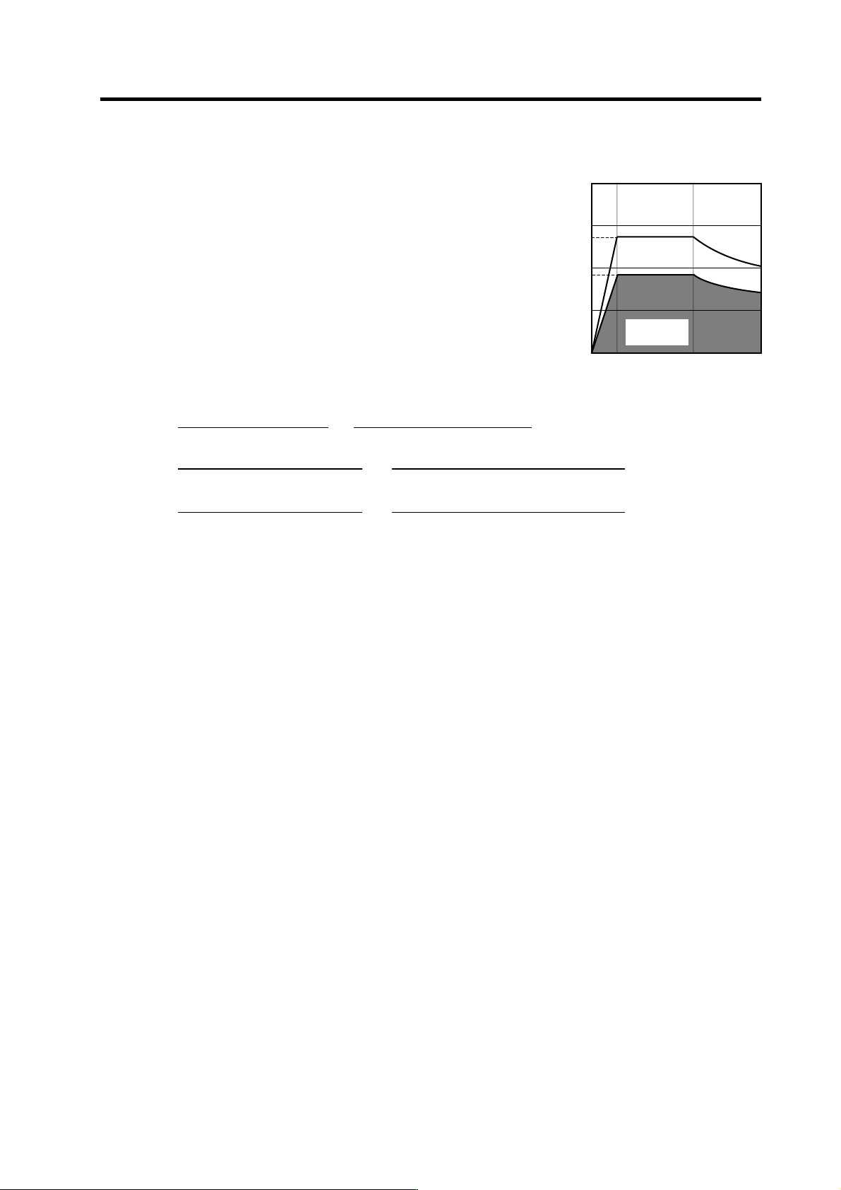
(1) Calculating the theoretical acceleration/deceleration time
Each theoretical acceleration/deceleration time is calculated
for each output range based on the spin dle motor output
characteristics as shown o n the right. Note that the load
torque (friction torque, etc.) is 0 in this calculatio n expression,
so the acceleration/deceleration time can be known as a
rough guide, but this calculation re sult differs from the
acceleration/deceleration time of the actual machine.
(a) Maximum motor output during
acceleration/deceleration : Po
During acceleration/decel eration operation, the motor
can output at 120% of the short-time rating. Thus, the
motor output Po in the constant output range during
acceleration/deceleration follows the expression below.
Po = (Short-time rated output) × 1.2 [W]
(b) Total load inertia: J
all
The inertia of the total load which is accelerated and decelerated follows the expression below.
J
all
= (Motor inertia) + (motor shaft conversion load inertia) [ kg•m
2
] (Caution 1)
The acceleration/deceleration time until the rotation speed "N" to be required is calculated for
each motor output range as shown below, using the values obtained in (a) and (b).
(c) Acceleration/deceleration time for constant torque range: t1···0 to N [r/min ] (0≤N≤N1)
(For N>N1, apply N=N1 and also calculate t2 or t3.)
1.097 x 10
-2
x J
all
x N1 x N
t1 =
Po
[s] (Caution 1)
(d) Acceleration/deceleration time for constant output range: t2···N1 to N [r/min] (N1<N≤N2)
(For N>N2, apply N=N2 and also calculate t3.)
1.097 x 10
-2
x J
all
x (N
2
- N1
2
)
t2 =
2 x Po
[s] (Caution 1)
(e) Acceleration/deceleration time in deceleration output range: t3···N2 to N [r/min]
(N2<N≤N3)
1.097 x 10
-2
x J
all
x (N
3
- N2
3
)
t3 =
3 x Po x N2
[s] (Caution 1)
Based on the above expression s, the acceleration/deceleration time: t from 0 to N3 [r/min] is:
t = t1 + t2 + t3 [s] (Caution 2)
CAUTION
1. Note that the inertia (J) is a quarter of "GD
2
".
Ex.) When "GD
2
" is 0.2 [kg・m
2
], the inertia is "0.2 ÷ 4 = 0.05 [kg・m
2
]".
2. If the AC input power voltage to the power supply is low, or if the input
power impedance is high, the accelerati on/deceleration time may be long.
(Especially, the acceleration/decele rati on time of the deceleration output
range may be long.)
Output [W]
Output characteristics for
acceleration/deceleration
0
N1
N2
0
N3
Po
Rotation speed [r/min]
Short-time rating
×
1.2
Constant
output range
Constant out
p
ut ran
g
e
Deceleration
range
5. Spindle Adjustment
5 - 28
[Calculation example]
Calculate the acceleration/deceleration time from 0 to
10000[r/min] for an spindle motor having the output
characteristics shown on the right when the motor inertia is
0.059 [kg・m
2
], and when the motor shaft conversi on load
inertia is 0.2 [kg
•m
2
].
Po = (Short-time rated output) x 1.2
= 5500 x 1.2 = 6600 [W]
J
all
= (Motor inertia) + (load inertia)
= 0.0148 + 0.05 =0.0648 [kg・m
2
]
1.097 x 10
-2
x J
all
x N1
2
1.097 x 10
-2
x 0.0648 x 1500
2
t1 =
Po
=
6600
= 0.242 [s]
1.097 x 10
-2
x J
all
x (N2
2
- N1
2
) 1.097 x 10
-2
x 0.0648 x (6000
2
- 1500
2
)
t2 =
2×Po
=
2×6600
= 1.818 [s]
1.097 x 10
-2
x J
all
x (N3
3
- N2
3
) 1.097 x 10
-2
x 0.0648 x (10000
3
- 6000
3
)
t3 =
3 x Po x N2
=
3 x 6600 x 6000
= 4.691 [s]
Thus,
t = t1 + t2 + t3 = 0.242 + 1.818 + 4.691 = 6.751 [s]
0
1500
6000
0
2.0
6.0
8.0
4.0
Output [kW]
10000
15-minute
rating
3.7
5.5
4.1
Continuous
rating
Rotation speed [r/min]
Spindle motor characteristics
2.8
5. Spindle Adjustment
5 - 29
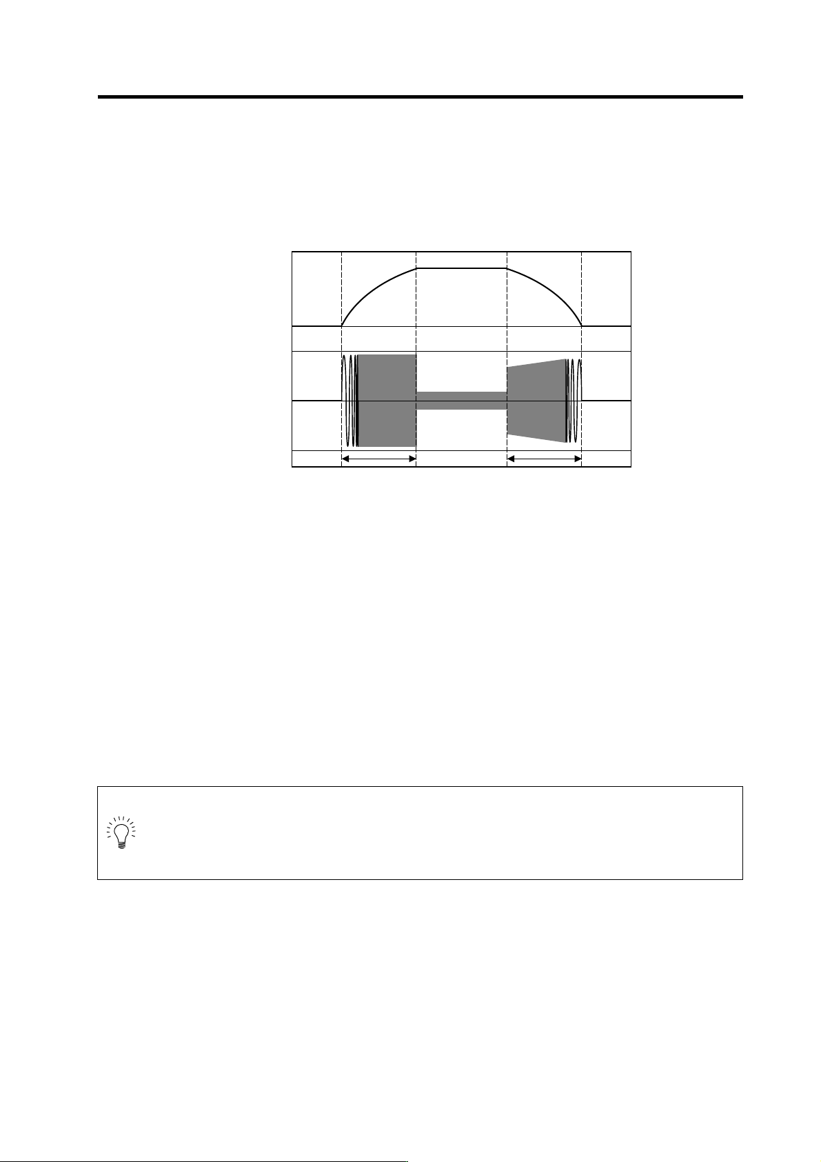
(2) Measuring the acceleration/deceleration waveforms
Measure the acceleration/deceleration waveforms by using the spindle drive unit's D/A output
function and check if theoretical acceleration/de celeration time is within ±15%. Refer to "5-1 D/A
output specifications for spindle drive unit" for details on D/A output functions.
Phase current FB output can be measured by the waveform for either U or V phase FB.
When acceleration/deceleration time does not match the theoretical value (an error rate 15% or
more), check the following items.
[1] There may be an error in calculating load inertia for the motor axis conversion used when
calculating the theoretical acceleration/deceleration time. Check the load inertia again.
[2] When acceleration time is long and deceleration time is short, friction torque is thought to be
large. Check load meter value at the maximum speed (spindle monitor screen). If the load is
10% or more, friction torque is thought to be relatively large. Mechanical friction, such as
bearing friction or timing belt friction, is assumed to be large. Measure the acceleration/
deceleration time again following trial run.
[3] Even if the problems above are not found, when acceleration/decel eration time does not match,
there may be a possibility of using spindle motor and spindle drive unit that are not specified, or
using wrong parameters. Check the spindle motor type and spindle drive unit type again, as
well as the spindle parameter settings.
POINT
1. There are cases where acceleration/d ecele ration waveforms cha nge dependin g
on the spindle temperature. Check the waveforms when the spindle temperature
is high (after continuous operation) and when it is low.
2. Conduct "3-5 Initial adjustment of spindle PLG" beforehand.
Speedometer output [V]
Acceleration/deceleratio n waveforms of spindle motor
0
4.0
2.5
1.0
U(V) phase current FB output [V]
Acceleration time: ta Deceleration time: td