bnp-b2365(eng)b.pdf - 第200页
4. Servo Adjustment 4 - 1 4-1 D/A output specificati ons for servo drive unit ............................................................................ ....... 4-2 4-1-1 D/A output spec ifications ....................…
3. Setup
3 - 112
3-6-4 Spindle end PLG automatic adjustment
Spindle end PLG automatic adjustment is a function that automatically adjusts the gain and offset of the
A and B phase sine wave signals of the spindle end PLG used for C axis control which are input into the
detector converter (MDS-B-PJEX) used in the MDS-C1- SPX/SPHX unit. The adjustment data is saved
in the detector converter, and is used to control the motor the next time the power is turned ON.
Always carry out this adjustment when starting up the spindle system, when the spindle motor has
been replaced, when the PLG has been replaced or readjusted, or when the detector converter has
been replaced. This function is used to improve the accuracy of the position data.
<Adjustment methods>
[1] If SP240 is set to 1, change it to 0, and turn the NC power ON again. If it is already set to 0, go
to step [2].
[2] If the SP240 setting is 0, change it to 1.
[3] Input forward run start. The spindle motor will automatically rotate at the adjustment speed
(two stages for offset adjustment and gain adjustment). (The control input 3/bit8 or bit9 is
changed to 1 after the forward run start input, and "D" is displayed for the drive unit until
automatic adjustment is completed.)
[4] The adjustment results will be calculated and the operation will automatically stop several
seconds after forward run is started. (When automatic adjustment is completed, the drive unit
display at the NC spindle monitor screen changes from "D" to "C". Even though the motor is
stopped while "D" is displayed, automatic adjustment is in progress. Be sure to wait until "C"
displays.)
[5] Turn forward run OFF. (The adjustment data will be saved.)
[6] Turn the NC power ON again.
No. Abbr. Parameter name Details
Setting range
(Unit)
Standard
setting
SP240 EXHS
PLG automatic
adjustment (PJEX)
<For MDS-C1-SPX/SPHX>
This validates the automatic adjustment function for the
PLG connected to the MDS-B-PJEX.
0 to 1
0 → 1
POINT
1. If the NC power is turned ON when SP240 is set to 1, the adjustment data
saved in the detector converter (MDS-B-PJEX) will be used for control.
2. To readjust, or to turn the start OFF during the automatic adjustment when
"D" is displayed for the drive unit (see step [4] above), specify another
SP205=0 setting to restart the NC, then perform the above procedure,
beginning from step [2].
CAUTION
1. The motor will automatically rotate at the adjustment speed during PLG
automatic adjustment. Do not touch the rotating sections as this is
hazardous.
2. Complete PLG adjustment before starting this adjustment.

4. Servo Adjustment
4 - 1
4-1 D/A output specifications for servo drive unit ................................................................................... 4-2
4-1-1 D/A output specifications ........................................................................................................... 4-2
4-1-2 Output data settings................................................................................................................... 4-3
4-1-3 Setting the output magnification ................................................................................................ 4-3
4-2 Gain adjustment................................................................................................................................ 4-4
4-2-1 Current loop gain ....................................................................................................................... 4-4
4-2-2 Speed loop gain ......................................................................................................................... 4-4
4-2-3 Position loop gain....................................................................................................................... 4-6
4-3 Characteristics improvement ............................................................................................................ 4-9
4-3-1 Optimal adjustment of cycle time............................................................................................... 4-9
4-3-2 Vibration suppression measures ............................................................................................. 4-11
4-3-3 Improving the cutting surface precision ................................................................................... 4-15
4-3-4 Improvement of characteristics during acceleration/deceleration ........................................... 4-19
4-3-5 Improvement of protrusion at quadrant changeover................................................................ 4-22
4-3-6 Improvement of overshooting .................................................................................................. 4-29
4-3-7 Improvement of the interpolation control path ......................................................................... 4-31
4-4 Adjustment during full closed loop control ...................................................................................... 4-33
4-4-1 Outline...................................................................................................................................... 4-33
4-4-2 Speed loop delay compensation.............................................................................................. 4-34
4-4-3 Dual feedback control (Optional function) ............................................................................... 4-35
4-5 Settings for emergency stop........................................................................................................... 4-37
4-5-1 Deceleration control................................................................................................................. 4-37
4-5-2 Vertical axis drop prevention control........................................................................................ 4-39
4-6 Protective functions ........................................................................................................................ 4-43
4-6-1 Overload detection................................................................................................................... 4-43
4-6-2 Excessive error detection ........................................................................................................ 4-43
4-6-3 Collision detection.................................................................................................................... 4-44
4. Servo Adjustment
4 - 2
CAUTION
"Chapter 4 Servo adjustment" explains the methods when controlling with the
high-gain specifications.
4-1 D/A output specifications for servo drive unit
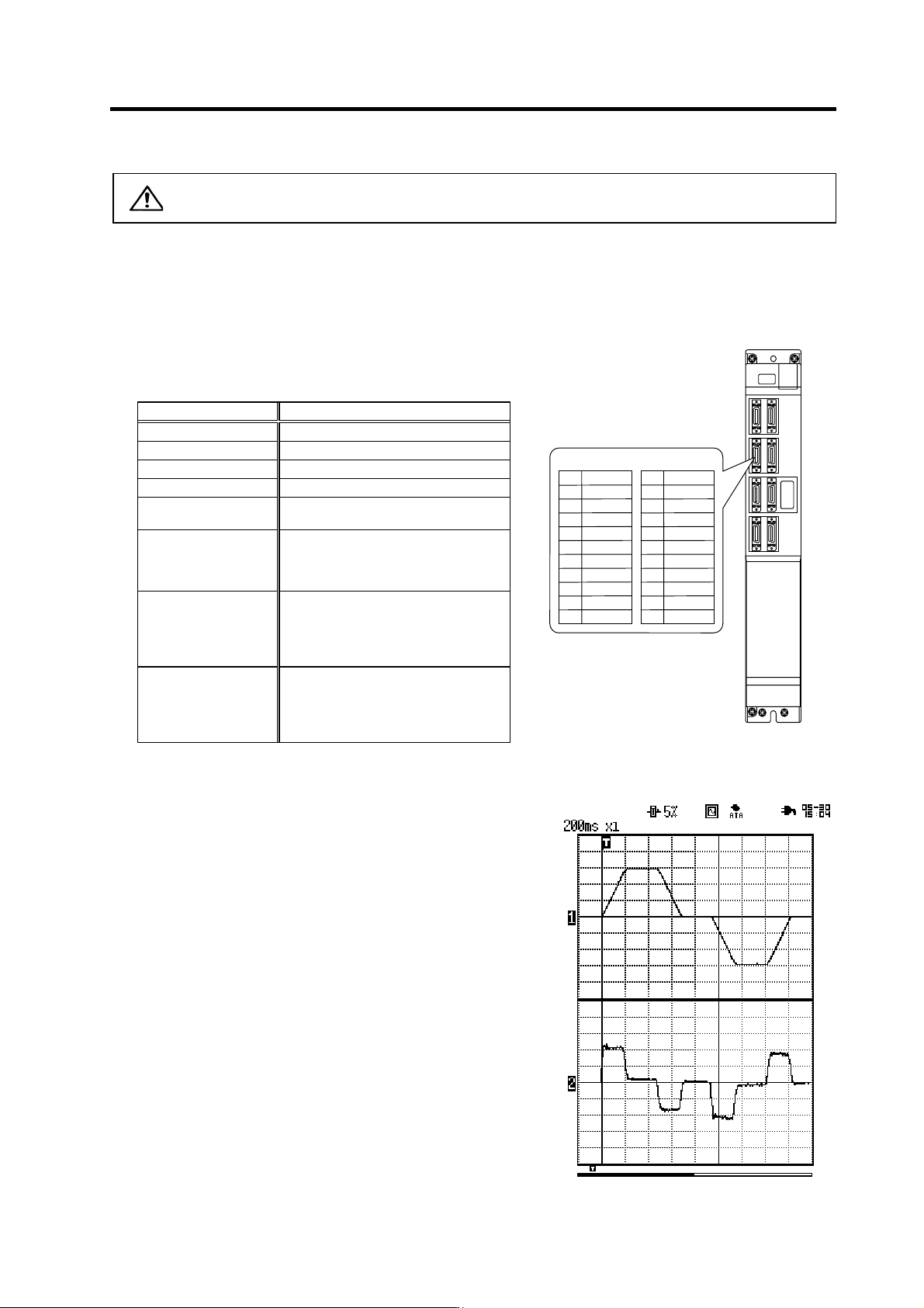
The MDS-C1-V1/V2 servo drive unit has a function to D/A output the various control data.
The servo adjustment data required for setting the servo parameters to match the machine can be D/A
output. Measure using a hi-coder, oscilloscope, etc.
4-1-1 D/A output specifications
Item Explanation
No. of channels 2ch
Output cycle 888µs (min. value)
Output precision 8bit
Output voltage range 0V to 2.5V (zero) to +5V
Output magnification
setting
±1/256 to ±128-fold
Output pin
CN9 connector
MO1 = Pin 9
MO2 = Pin 19
GND = Pins 1, 11
Function
Phase current feedback output function
L axis U phase current FB : Pin 7
L axis V phase current FB : Pin 17
M axis U phase current FB : Pin 6
M axis V phase current FB : Pin 16
Others
The D/A output for the 2-axis unit
(MDS-C1-V2) is also 2ch. When using
the 2-axis unit, set -1 for the output
data (SV061, 62) of the axis that is not
to be measured.
With the MDS-C1-V1/V2 Series, there is a 2.5V offset voltage (2.5V when data is 0), so the zero level
position must be adjusted on the hi-corder side.
+2.5 [V]
0 [V]
Speed FB
Single
shot
Current FB
+2.5 [V]
0 [V]
+5 [V]
+5 [V]
Scroll
Memory
Example of D/A out pu t wa veform
MO19
Name
LG
LUIFB
MUIFB
2
5
1
Pin
6
4
3
10
7
8
CN9 connector
MO2 19
Name
LG
LVIFB
MVIFB
12
15
11
Pin
16
14
13
20
17
18