bnp-b2365(eng)b.pdf - 第244页
4. Servo Adjustment 4 - 45 (2) Collision detection method 2 When the current comman d reaches the motor's ma ximum current, the moto r will decelerate and stop at a torque 80% (standard value) of the moto r's m…
4. Servo Adjustment
4 - 44
4-6-3 Collision detection
Collision detection quickly detects a collision of the motor shaft, and decelerates and stops the motor.
This suppresses the generation of an excessive torque in the machine tool, and helps to prevent an
abnormal state from occurring. Impact at a collision will not be prevented by using this collision
detection function, so this function does not necessarily guarantee that the machine tool will not be
damaged or that the machine accuracy will be maintained after a collision. The same caution as during
regular operation is required to prevent the machine from colliding.
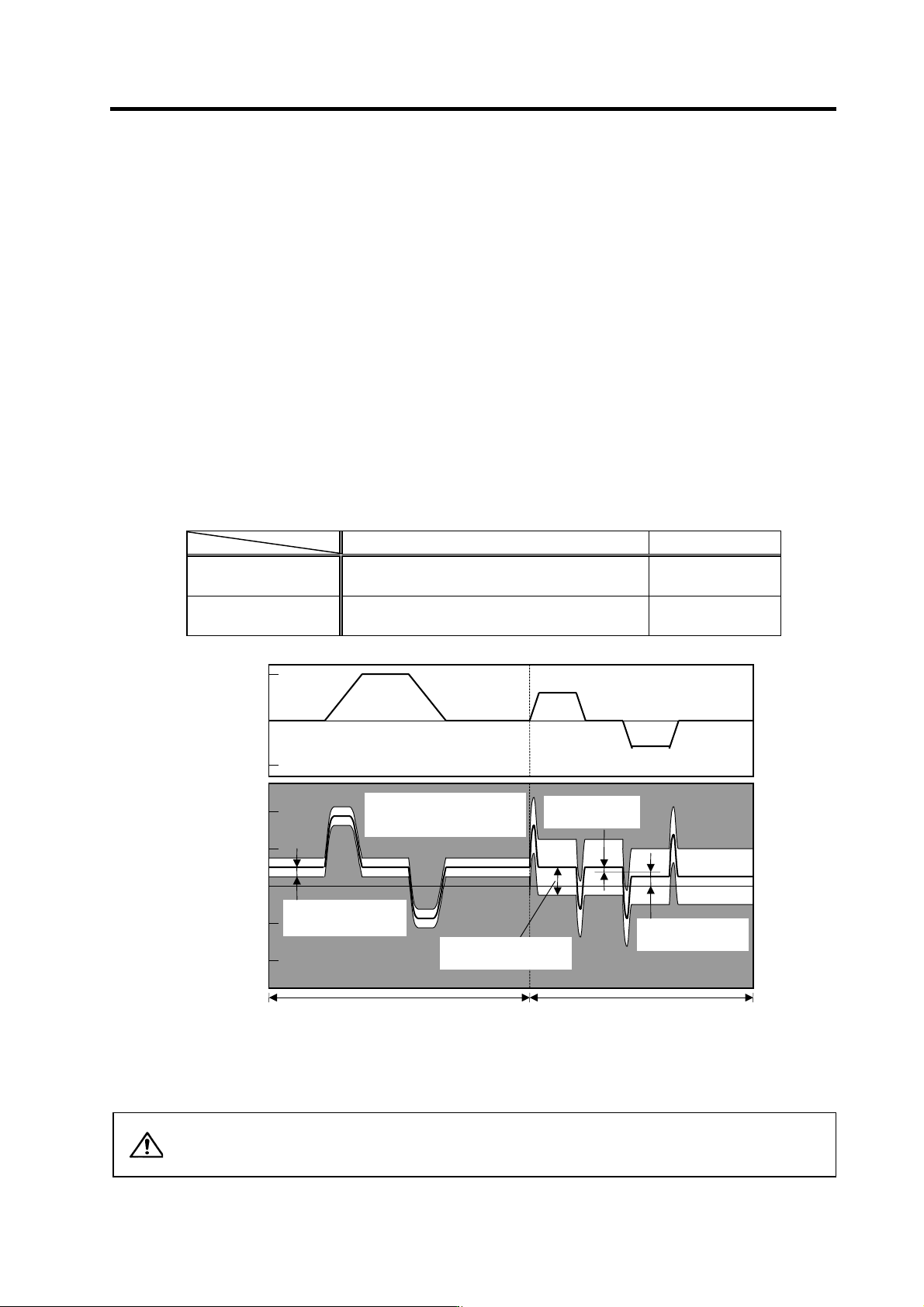
(1) Collision detection method 1
The required torque for the command is estimated from the position command issued from the NC,
and the disturbance torque is obtained from the difference with the actual torque. When this
disturbance torque exceeds the collision detection level set with the parameters, the motor will
decelerate to a stop with a torque 80% (standard) value of the motor's maximum torque. After
decelerating to a stop, alarm 58 or 59 will occur, and the system will stop.
The collision detection level for rapid traverse (G0) is set with SV060: TLMT. The collision
detection level for cutting feed (G1) is set to 0 to 7-fold (SV35.clG1) based on the collision
detection level for rapid traverse. When clG1 is set to 0, collision detection method 1 will not
function during cutting feed. If SV060 is set to 0, all collision detection (including methods 1 and 2)
will not function.
Collision detection level setting parameter Detected alarm
During rapid traverse
(During G0 feed)
SV060 Alarm 58
During cutting feed
(During G1 feed)
SV060 × c1G1 (SV035) Alarm 59
Alarm detection range for collision detection method 1
CAUTION
The collision detection function does not guarantee safety or machine
accuracy when a collision occurs. Thus, the same caution as during regular
operation is required to prevent the machine from colliding.
Speed command
(r/min)
0
Estimated torque
(stall%)
0
3000
200
100
-200
-100
-3000
Unbalance torque
(SV032)
G0 collision detection
level (SV060)
Collision detection method 1,
detection range
(alarm 58/59)
Frictional torque
(SV045)
G1 feed
(
cuttin
g
feed
)
G0 feed
(
ra
p
id traverse
)
G1 collision detection
level
(
SV060×clG1
)
4. Servo Adjustment
4 - 45
(2) Collision detection method 2
When the current command reaches the motor's maximum current, the motor will decelerate and
stop at a torque 80% (standard value) of the motor's maximum torque. After decelerating to a stop,
alarm 5A will occur, and the system will stop. If the acceleration/deceleration time constant is short
and incorrect detections easily occur during normal operation, lengthen the acceleration/
deceleration time constant and adjust so that the current is not saturated (does not reach the
maximum current) during acceleration.
If the acceleration/deceleration time constant cannot be lengthened, set parameter SV035/bitF
(SSF4.c12n) to 1 to ignore collision detection method 2.
POINT
1. Always validate SHG control when using the collision detection function, or
when carrying out SV059 setting value operation.
2. Provide an allowance in the detection level setting to prevent incorrect
detections.
3. All collision detection functions will be disabled when SV60 is set to 0.
4. Collision detection method 2 will function if a value other than 0 is set in
SV060. Note that the detection can be ignored by setting the parameter
(SV035/bitB).
5. The torque estimated gain (SV059) must be readjusted when there are
changes in the detector resolution following the detector replacement, or in
the detector loop gain (PGN) or position control system. (closed loop control
and semi-closed loop has been changed).
<Setting and adjustment methods>
[1] Confirm that SHG control is active. Collision detection function is valid only during SHG control.
[2] Set the axis unbalanced torque to the torque offset (SV032: TOF). (Refer to "4-3-5 (1)
Unbalance torque and frictional torque" for details on measuring the unbalance torque.)
[3] Measure the frictional torque and set in the frictional torque (SV045: TRUB). Carry out
reciprocation operation (approx. F1000) with the axis to be adjusted, and measure the load
current % when the axis is fed at the constant speed on the NC SERVO MONITOR screen.
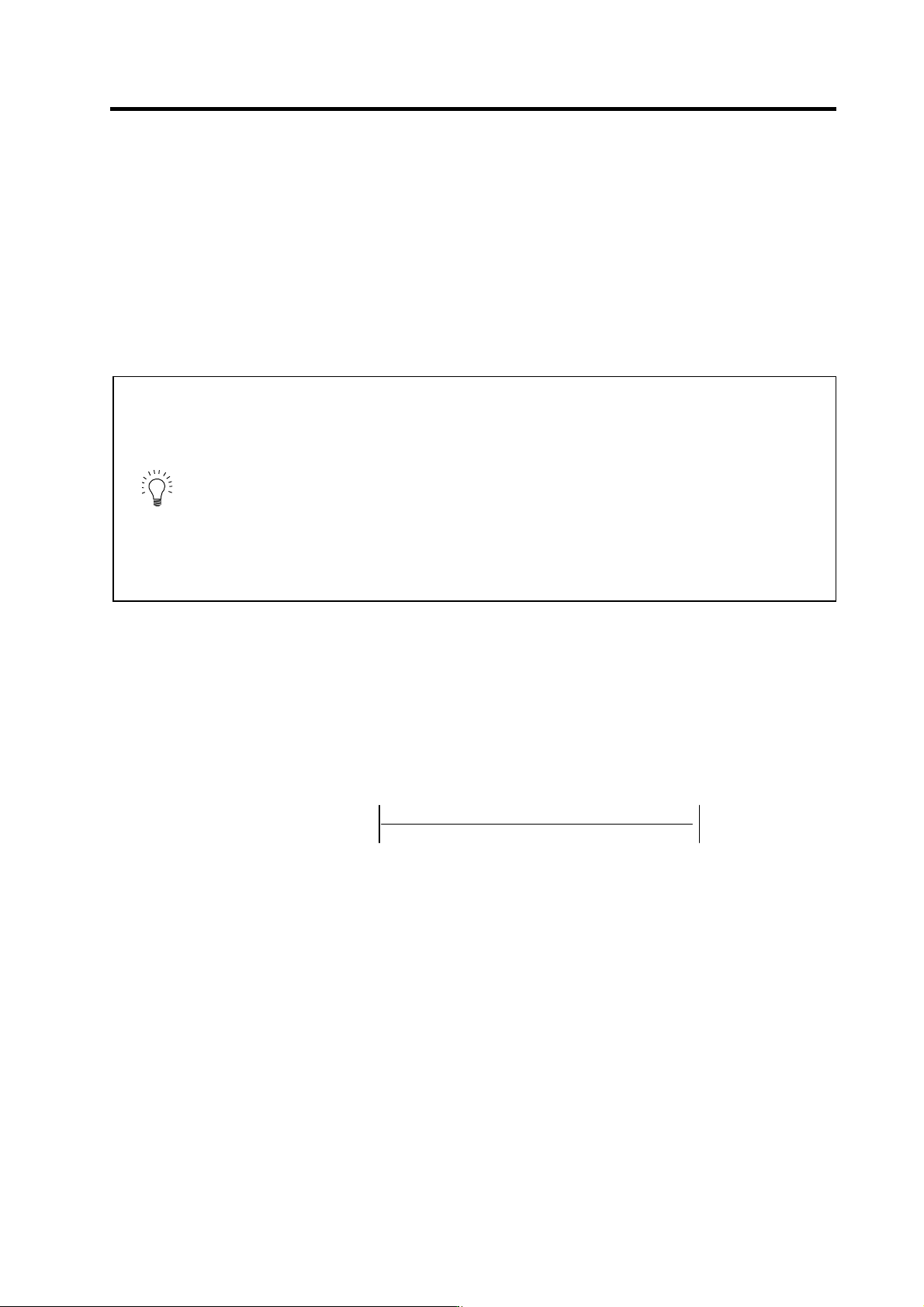
This frictional torque is expressed with the following expression.
[4] Set SV035: SSF4.clt (bitF) to 1 for the axis being adjusted, and move in both directions with
JOG, etc., at the rapid traverse rate. When the MPOS display on the NC SERVO MONITOR
screen has stabilized, set that value for the torque estimated gain (SV059: TCNV). Return
SV035: SSF4.clt (bitF) to 0.
[5] If the acceleration/deceleration time is short, and the current is limited, set SV035: SSF4.c12n
(bitB) to 1 to invalidate collision detection method 2.
[6] Adjust the collision detection level (SV060: TLMT). First set 100. If operation at the rapid
traverse rate results in an alarm, increase the setting value by approx. 20. If an alarm does not
occur, lower the setting value by approx. 10. When SV035: SSF4.clet (bitA) is set to 1, the
estimated disturbance torque peak value for the latest two seconds will appear at MPOS. This
value can be used as reference. Set the final setting value to a value approx. 1.5-fold the limit
value at which an alarm does not occur.
[7] Divide the maximum cutting load with the value set for the collision detection level (SV060:
TLMT). (Round up the decimal) Set this value in SV035: SSF4.clG1 (bitC-E).
2
(+ feed load current %) - (- feed load current %)
Frictional tor
q
ue
(
%
)
=
4. Servo Adjustment
4 - 46
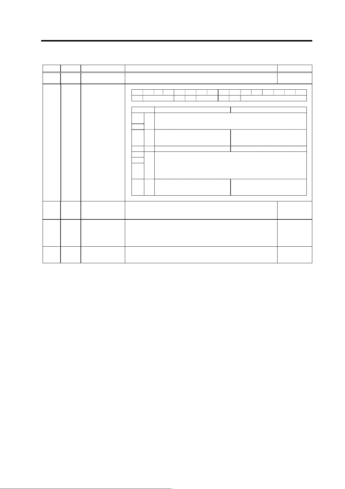
No. Abbrev. Parameter name Explanation Setting range
SV032 TOF Torque offset
Set the unbalance torque of vertical axis and inclined axis. -100 to 100
(Stall current %)
SV035 SSF4 Servo function
selection 4 F E D C B A 9 8 7 6 5 4 3 2 1 0
clt clG1 cl2n clet cltq iup tdt
bit Meaning when "0" is set Meaning when "1" is set
8
Set the retracting torque for collision detection in respect to the maximum
torque of the motor.
9
cltq
00 : 100% 01 : 90% 10 : 80% (Standard) 11 : 70%
A clet
Setting for normal use The disturbance torque peak of the
latest two seconds is displayed in
MPOS of the servo monitor screen.
B cl2n Collision detection method 2 valid Collision detection method 2 invalid
C
D
E
clG1
Collision detection method 1
Set the collision detection level during cutting feed (G1).
The G1 collision detection level=SV060
× clG1.
When clG1=0, the collision detection method 1 during cutting feed won’t
function.
F clt
Setting for normal use The guide value of the SV059
setting value is displayed in MPOS
of the servo monitor screen.
SV045 TRUB
(Low
order)
Frictional torque
When you use the collision detection function, set the frictional torque. 0 to 100
(Stall current %)
SV059 TCNV Collision detection
torque estimating
gain
Set the torque estimating gain when using the collision detection function.
After setting as SV035/bitF(clt)=1 and performing
acceleration/deceleration, set the value displayed in MPOS of the NC
servo monitor screen.
Set to "0" when not using the collision detection function.
-32768 to
32767
SV060 TLMT Collision detection
level
When using the collision detection function, set the collision detection
level during the G0 feeding.
If "0" is set, none of the collision detection function will work.
0 to 999
(Stall current %)