bnp-b2365(eng)b.pdf - 第170页
3. Setup 3 - 83 No. Abbr. Parameter name Details Setting rang e (Unit) Standard setting SP044 TRANS* NC communication frequency Set a frequency of data communication with NC. 0 to 32767 Standard: 0 Special: 1028 SP045 CS…
3. Setup
3 - 82
No. Abbr. Parameter name Details
Setting range
(Unit)
Standard
setting
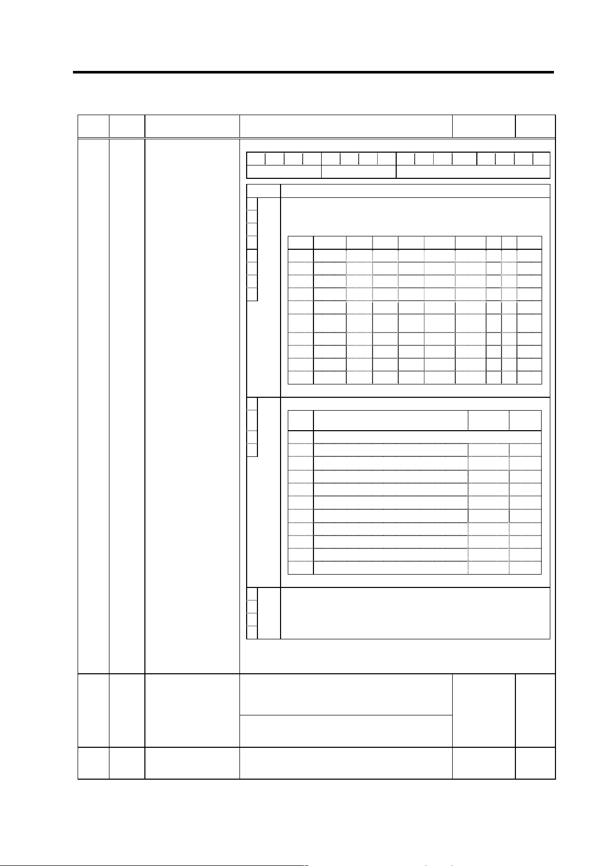
F E D C B A 9 8 7 6 5 4 3 2 1 0
amp rtyp ptyp
bit Explanation
0
1
2
When the CN4 connector of the drive unit and the power supply are
connected, setting below is necessary.
To validate the external emergency stop function, add 40h.
3
Setting 0x 1x 2x 3x 4x 5x 6x 7x 8x
4
x0 Not used CV-300
5
x1 CV-110 CR-10
6
x2 CV-220 CR-15
7
ptyp
x3 CR-22
x4 CV-37 CR-37
x5 CV-150
MDS-B-
CVE-450
MDS-B-
CVE-550
x6 CV-55 CV-260 CR-55
x7 CV-370
x8 CV-75 CR-75
x9 CV-185 CR-90
SP041 PTYP* Power supply type
8
Set the regenerative resistor type when MDS-A-CR is used.
9 Setting Regenerative resistor model name
Resistance
value
Capacity
A0
MDS-C1-CV (Setting when using power supply regeneration)
B
rtyp
1
GZG200W260HMJ (Note)
26Ω
80W
2
GZG300W130HMJ×2
26Ω
150W
3
MR-RB30
13Ω
300W
4
MR-RB50
13Ω
500W
5
GZG200W200HMJ×3
6.7Ω
350W
6
GZG300W200HMJ×3
6.7Ω
500W
7
R-UNIT-1
30Ω
700W
8
R-UNIT-2
15Ω
700W
9
R-UNIT-3
15Ω
2100W
A~F
No setting
C
D
E
F
amp
Always set to "0".
(Note) When MDS-B-SP-370, 450 or 550 is used, set "0" even if power
regeneration type is applied.
<For MDS-C1-SP/SPH/SPM>
This parameter is used to set the C-axis detector range.
Set "0" for this parameter.
"2" is used by Mitsubishi for testing.
SP042 CRNG* C-axis detector range
<For MDS-C1-SPX/SPHX>
Set the number of pulses for the spindle end PLG.
"4" = 128, "5" = 256, "6" = 512, "8" = 180
0 to 8 0
SP043 TRNG*
Synchronous tapping,
spindle synchronous
detector range
This parameter is used to set the synchronous tapping or
spindle synchronous detector range.
Set "0" for this parameter.
0 to 7 0
Parameters with an asterisk * in the abbreviation, such as OSP*, are validated with the NC power turned ON again.
3. Setup
3 - 83
No. Abbr. Parameter name Details
Setting range
(Unit)
Standard
setting
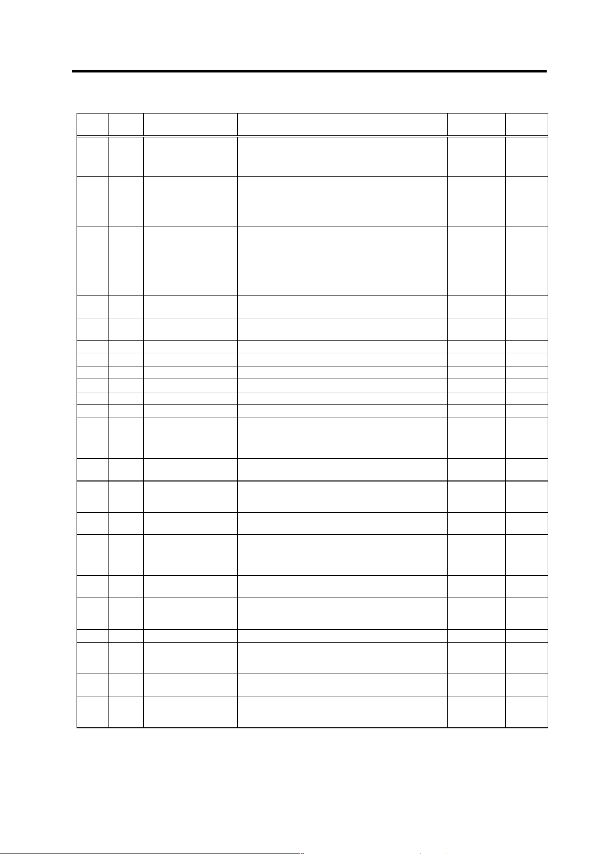
SP044 TRANS*
NC communication
frequency
Set a frequency of data communication with NC.
0 to 32767
Standard:
0
Special:
1028
SP045 CSNT Dual cushion timer
Set the cycle to add the increment values in the dual
cushion process.
When this setting value is increased, the dual cushion will
increase, and the changes in the speed during
acceleration/deceleration will become gradual.
0 to 1000 (ms) 0
SP046 CSN2*
Speed command dual
cushion
For an acceleration/deceleration time constant defined in
SP019 (CSN1) , this parameter is used to provide smooth
movement only at the start of acceleration/deceleration.
As the value of this parameter is smaller, it moves
smoother but the acceleration/deceleration time becomes
longer.
To make this parameter invalid, set "0".
0 to 1000 0
SP047 SDTR*
Speed detection reset
value
Set the reset hysteresis width for a speed detection set
value defined in SP020 (SDTS).
0 to 1000
(r/min)
30
SP048 SUT* Speed reach range
Set the speed deviation rate with respect to the
commanded speed for output of the speed reach signal.
0 to 100 (%) 15
SP049 TLM2 Torque limit 2 Set the torque limit rate for the torque limit signal 010. 0 to 120 (%) 20
SP050 TLM3 Torque limit 3 Set the torque limit rate for the torque limit signal 011. 0 to 120 (%) 30
SP051 TLM4 Torque limit 4 Set the torque limit rate for the torque limit signal 100. 0 to 120 (%) 40
SP052 TLM5 Torque limit 5 Set the torque limit rate for the torque limit signal 101. 0 to 120 (%) 50
SP053 TLM6 Torque limit 6 Set the torque limit rate for the torque limit signal 110. 0 to 120 (%) 60
SP054 TLM7 Torque limit 7 Set the torque limit rate for the torque limit signal 111. 0 to 120 (%) 70
SP055 SETM*
Excessive speed
deviation timer
Set the timer value until the excessive speed deviation
alarm is output.
The value of this parameter should be longer than the
acceleration/deceleration time.
0 to 160 (s) 12
SP056 PYVR
Variable excitation
(min value)
Set the minimum value of the variable excitation rate.
Select a smaller value when gear noise is too high.
0 to 100 (%) 50
SP057 STOD*
Constant → transition
judgment value
Set the value for judging when changing the speed
command from a constant to acceleration/deceleration.
When "0" is set, judge the speed with 12 r/min.
0 to 50 (r/min) 0
SP058 SDT2*
Speed detection setting
value 2
Set the motor speed for carry out speed detection 2
output.
0 to 32767
(r/min)
0
SP059 MKT*
Winding changeover
base shut-off timer
Set the base shut-off time for contactor switching at coil
changeover.
Note that the contactor may be damaged with burning if
the value of this parameter is too small.
50 to 10000
(ms)
150
SP060 MKT2*
Current limit timer after
coil changeover
Set the current limit time to be taken after completion of
contactor switching at coil changeover.
0 to 10000
(ms)
500
SP061 MKIL*
Current limit value after
coil changeover
Set the current limit value during a period defined in
SP060 (MKT2) after completion of contactor switching at
coil changeover.
0 to 120 (%) 75
SP062 Not used. Set to "0". 0 0
SP063 OLT*
Overload alarm detection
time
Set the time constant for detection of the motor overload
alarm.
(For machine tool builder adjustment)
0 to 1000 (s) 60
SP064 OLL*
Overload alarm detection
level
Set the detection level of the motor overload alarm.
(For machine tool builder adjustment)
0 to 120 (%) 110
SP065 VCGN1*
Target value of variable
speed loop proportional
gain
Set the magnification of speed loop proportional gain with
respect to SP022 (VGNP1) at the maximum motor speed
defined in SP017 (TSP).
0 to 100 (%) 100
Parameters with an asterisk * in the abbreviation, such as OSP*, are validated with the NC power turned ON again.
3. Setup
3 - 84
No. Abbr. Parameter name Details
Setting range
(Unit)
Standard
setting
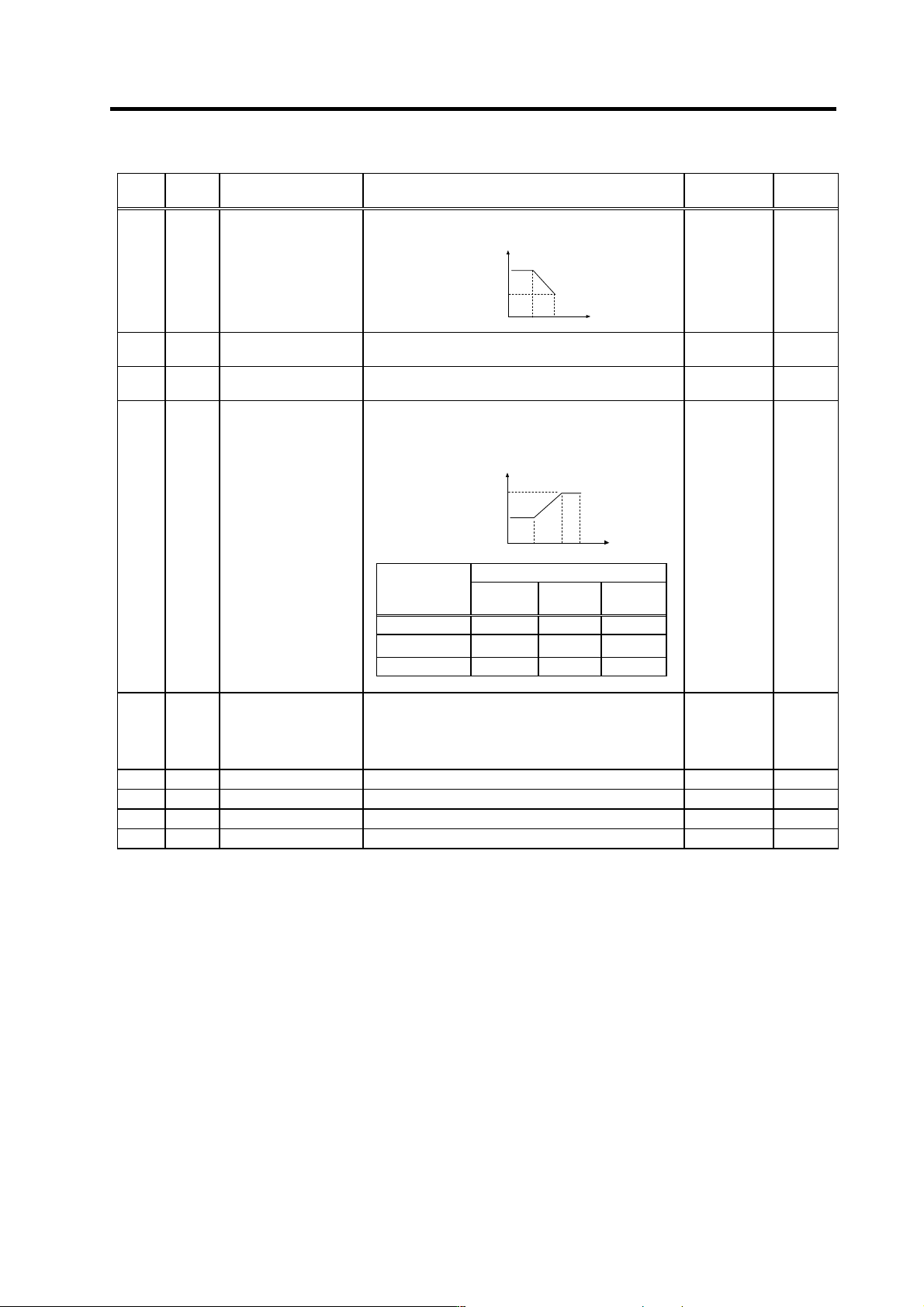
SP066 VCSN1*
Change starting speed of
variable speed loop
proportional gain
Set the speed when the speed loop proportional gain
change starts.
SP066 SP017
SP022
SP022×
(SP065/100)
Proportional gain
Speed
0 to 32767
(r/min)
0
SP067 VIGWA*
Change starting speed of
variable current loop gain
Set the speed where the current loop gain change starts. 0 to 32767
(r/min)
0
SP068 VIGWB*
Change ending speed of
variable current loop gain
Set the speed where the current loop gain change ends. 0 to 32767
(r/min)
0
SP069 VIGN*
Target value of variable
current loop gain
Set the magnification of current loop gain (torque
component and excitation component) for a change
ending speed defined in SP068 (VIGWB).
When this parameter is set to "0", the magnification is 1.
SP067 SP017SP068
Speed
1-fold
SP069×(1/16)-fold
0 to 32767
(1/16-fold)
0
SP070 FHz
Machine resonance
suppression filter
frequency
When machine vibration occurs in speed and position
control, set the frequency of the required vibration
suppression.
Note that a value of 100Hz or more is set.
Set to "0" when not used.
0 to 3000 (Hz) 0
SP071 VR2WA* Fixed control constant Set by Mitsubishi. Set "0" unless designated in particular. 0 0
SP072 VR2WB* Fixed control constant Set by Mitsubishi. Set "0" unless designated in particular. 0 0
SP073 VR2GN* Fixed control constant Set by Mitsubishi. Set "0" unless designated in particular. 0 0
SP074 IGDEC* Fixed control constant Set by Mitsubishi. Set "0" unless designated in particular. 0 0
Parameters with an asterisk * in the abbreviation, such as OSP*, are validated with the NC power turned ON again.
Setting value
SP017 (TSP)
Maximum
motor speed
SP067
(VIGWA)
SP068
(VIGWB)
SP069
(VIGN)
0 to 6000 0 0 0
6001 to 8000
5000 8000 45
8001 or more 5000 10000 64