bnp-b2365(eng)b.pdf - 第80页
2. Wiring and Connection 2 - 41 2-6-2 Dynamic brake unit wiring The 11kW and larger servo drive unit does not have bu ilt-in dynamic brakes. Always install a dynamic brake unit. The 9kW and smaller servo drive unit has b…
2. Wiring and Connection
2 - 40
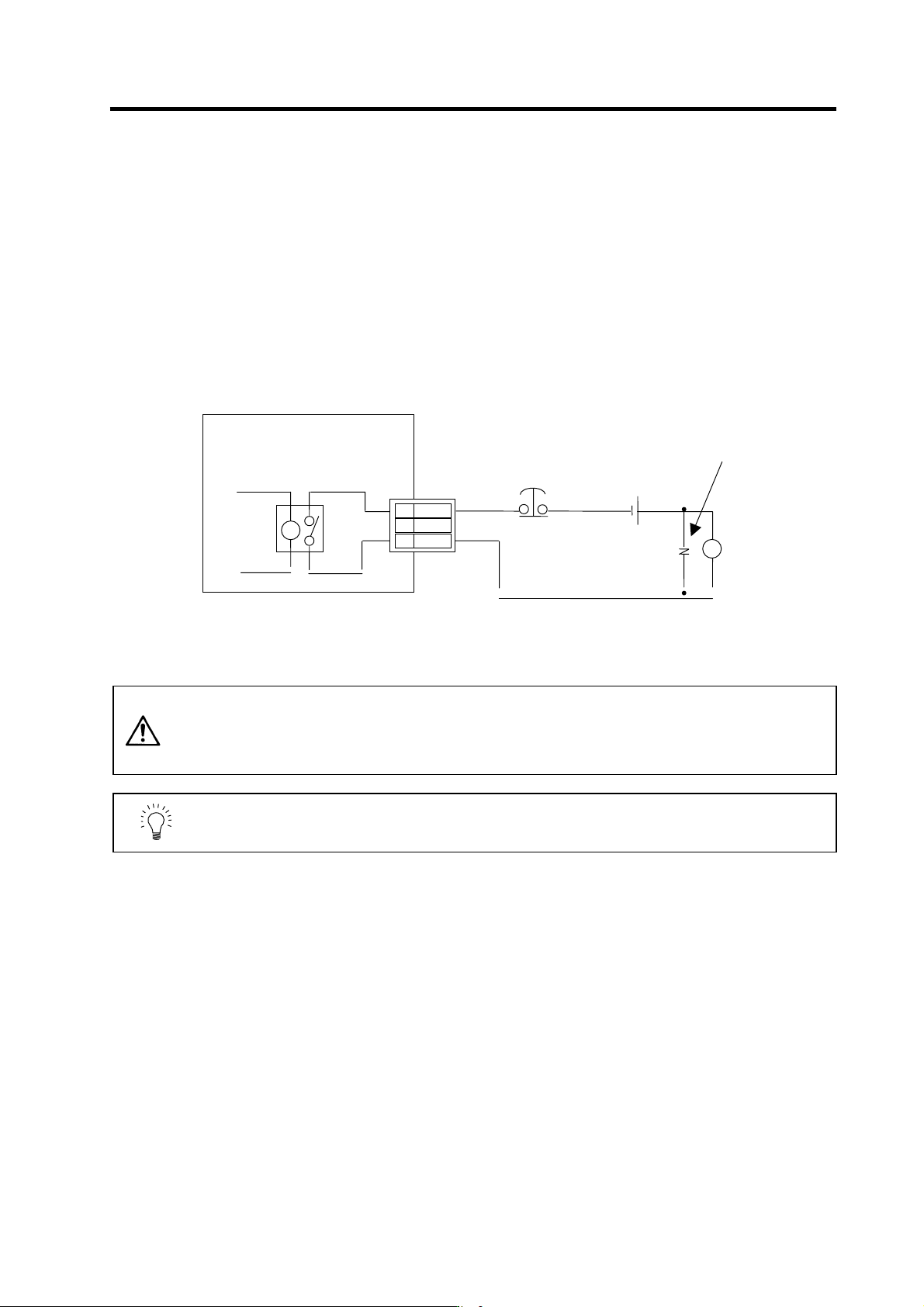
(3) Operation sequences when an emergency stop occurs
The motor brake control output operation when an emergency stop occurs differs according to the
motor deceleration stop method. Refer to section "4-5 Setting for emergency stop" for details on the
operation sequences for each stop method.
(4) Motor brake control connector (CN20) output circuit
As shown in the illustration below, an external power supply circuit is controlled by the CN20
connector output. Dynamic brake unit is controlled simultaneously for large-capacity drive unit
(MDS-C1-V1-110/150). Refer to "2-6-2 Dynamic brake unit wiring" for details.
(Unit internal relay specification: 5A 30Vdc/8A 250Vac)
CAUTION
1. Always install a surge absorber near the motor's brake terminal to eliminate
noise and protect the contacts.
2. The brakes cannot be released just by connecting the CN20 and motor brake
terminal. 24VDC must be supplied.
POINT
To ensure safety in an emergency, make sure that the magnetic brakes are
applied in sequence with the emergency stop switch.
A
lways install a surge
absorber
Brake
MDS-C1-V1/V2
3 MBR2
2
DBR
1 MBR1
CN20
24VDC
Surge
absorber
Emergenc
y
stop switch
2. Wiring and Connection
2 - 41
2-6-2 Dynamic brake unit wiring
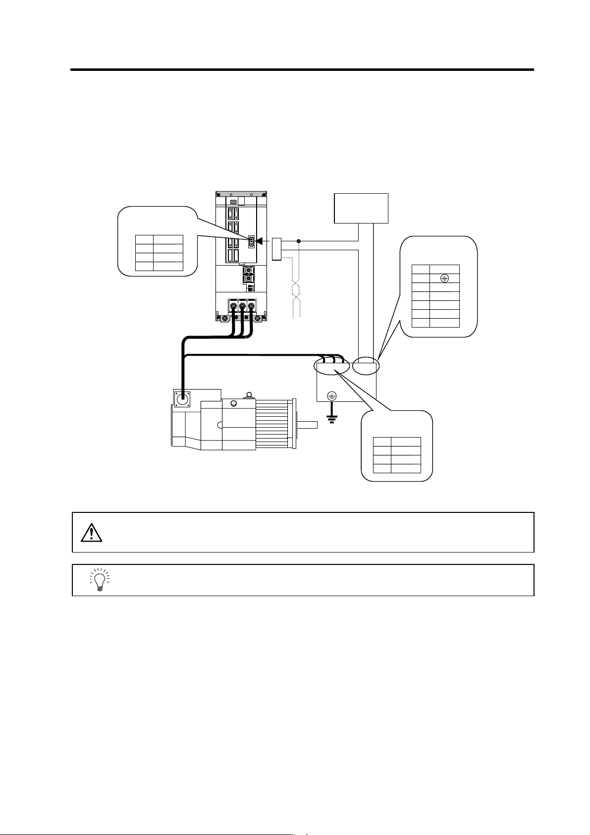
The 11kW and larger servo drive unit does not have built-in dynamic brakes. Always install a dynamic
brake unit.
The 9kW and smaller servo drive unit has built-in dynamic brakes.
CAUTION
Correct wire the dynamic brake unit to the servo drive unit.
Do not use for applications other than emergencies (normal braking, etc.). The
internal resistor could heat up, and lead to fires or faults.
POINT
When you use a servomotor with a brake, please wire (between 1pin and 3pin)
of CN20 connector.
Control terminal
block
(M3)
U V W
CNU20S(AWG14)
a b
Name
NC
a
2
1
Pin
3
b 4
5
6
13
14
External
power supply
24VDC GND
Dynamic brake unit
(MDS-B-DBU-150)
Drive terminal
block
(M3)
Name
V
W
2
1
Pin
3
U
1
2
3
Motor with a brake
Twist wire
Brake connector
(CN20)
Name
24VDC
DBU
MBR
2
1
Pin
3
Servomotor
MDS-C1-V1-110/150
2. Wiring and Connection
2 - 42
2-7 Peripheral control wiring
2-7-1 Input/output circuit wiring
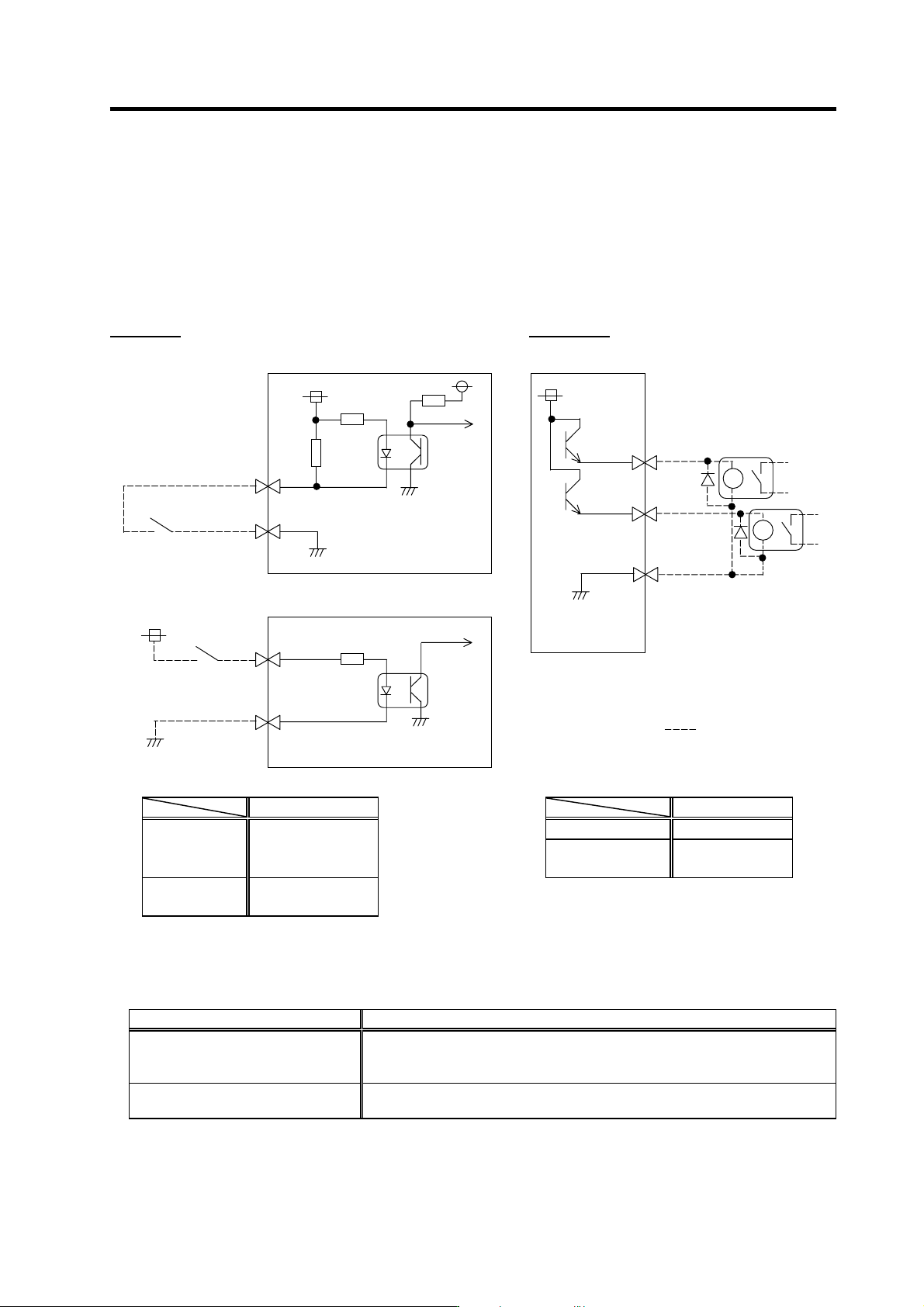
The input/output circuit to control the external signal such as external emergency stop input and relay
changeover signal output is wired.
The input/output circuit for each unit is as follows.
Input circuit Output circuit
For a switch or relay to be wired, use a switch or relay that satisfies the input/output (voltage, current)
conditions.
Interface name Selection example
For digital input signal (CN23,CN9)
Use a minute signal switch which is stably contacted and operated even with low
voltage or current
<Example> OMRON: G2A, G6B type, MY type, LY type
For digital output signal (CN9)
Use a compact relay operated with rating of 24VDC, 50mA or less.
<Example> OMROM: G6B type, MY type
Input condition
Output condition
Output voltage 24VDC ±5%
Switch ON
18VDC to 25.2VDC
9mA or more
Tolerable output
current Io
50mA or less
Switch OFF
4VDC or less
2mA or less
20
10
CN9 connector
Servo/spindle
drive unit
Switch
33.3k
24V
10k
1
3
CN23 connector
Power supply unit
Switch
24V
2k
Servo/spindle
drive unit
8
10
CN9 connector
18
MPO1
MPO2
MPI1
24G
24G
Relay, etc.
24V
The part indicated by the " " must be prepared
by the user.