bnp-b2365(eng)b.pdf - 第43页
2. Wiring and Connection 2 - 4 2-2 Main circuit terminal block/control circuit connector 2-2-1 Names and applications of main circuit terminal block signals and control circuit connectors The following table shows the de…
2. Wiring and Connection
2 - 3
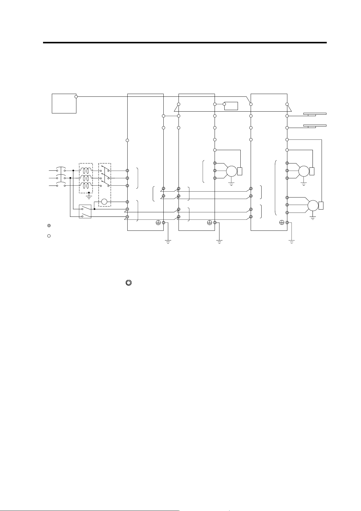
2-1 Part system connection diagram
MC1
Mitsubishi CN C
SV1,2
(CSH21)
External emergency
stop input
T
S
R
Contacto
r
No-fuse
breaker
Ground
: Main circuit
: Control circuit
CN1A
CN23
CN4
CN9
L1
L2
L3
L11
TE3
TE1
CN9
CN1B
L+
L-
U
V
W
CN6
CN5
TE1
PLG
Spindle drive unitPower supply unit
Spindle
motor
CN4
TE3
TE2
L+
L-
L11
L21
TE2
AC
reactor
Ground
Ground
L21
CN8
CN7
CN1A
CN4
CN9
CN20
CN1B
MU
MV
MW
CN2L
CN2M
LU
LV
LW
TE1
Motor end
detector
Motor end
detector
Battery unit
Servo drive unit
Servo
motor
Servo
motor
Tool end detecto
r
Tool end detecto
r
TE3
TE2
L+
L-
L11
L21
Ground
CN3M
CN3L
CN1A
MC
Breaker
SH21 cable
SH21 cable
(Note 1) The total length of the SH21 cable must be within 30m.
(Note 2) The connection method will differ according to the used motor.
(Note 3) When not using a battery unit, connect the terminal connector (R-TM).
(Note 4) The main circuit (
) and control circuit ({) are safely separated.
2. Wiring and Connection
2 - 4
2-2 Main circuit terminal block/control circuit connector
2-2-1 Names and applications of main circuit terminal block signals and control circuit
connectors
The following table shows the details for each terminal block signal.
Name Signal name Description
L1
.
L2
.
L3
Main circuit power
supply
Main circuit power supply input terminal
Connect a 3-phase 200VAC/200 to 230VAC, 50/60Hz power supply.
L11
L21
Control circuit power
supply
Control circuit power supply input terminal
Connect a single-phase 200VAC/200 to 230VAC, 50/60Hz power supply.
MC1
Contactor control
Contactor control terminal
The MC1 terminal has the same phase as L21. Connect to a different phase than the
phase connected to L21.
U
.
V
.
W
Motor output
(Single-axis unit)
Servo/spindle motor power output terminal
The servo/spindle motor power terminal (U, V, W) is connected.
LU
.
LV
.
LW
MU
.
MV
.
MW
Motor output
(Dual-axis unit)
Servo motor power output terminal (L-axis/M-axis)
The servo/spindle motor power terminal (U, V, W) is connected.
Protective grounding
(PE)
Grounding terminal
The servomotor/spindle motor grounding terminal is connected and grounded.
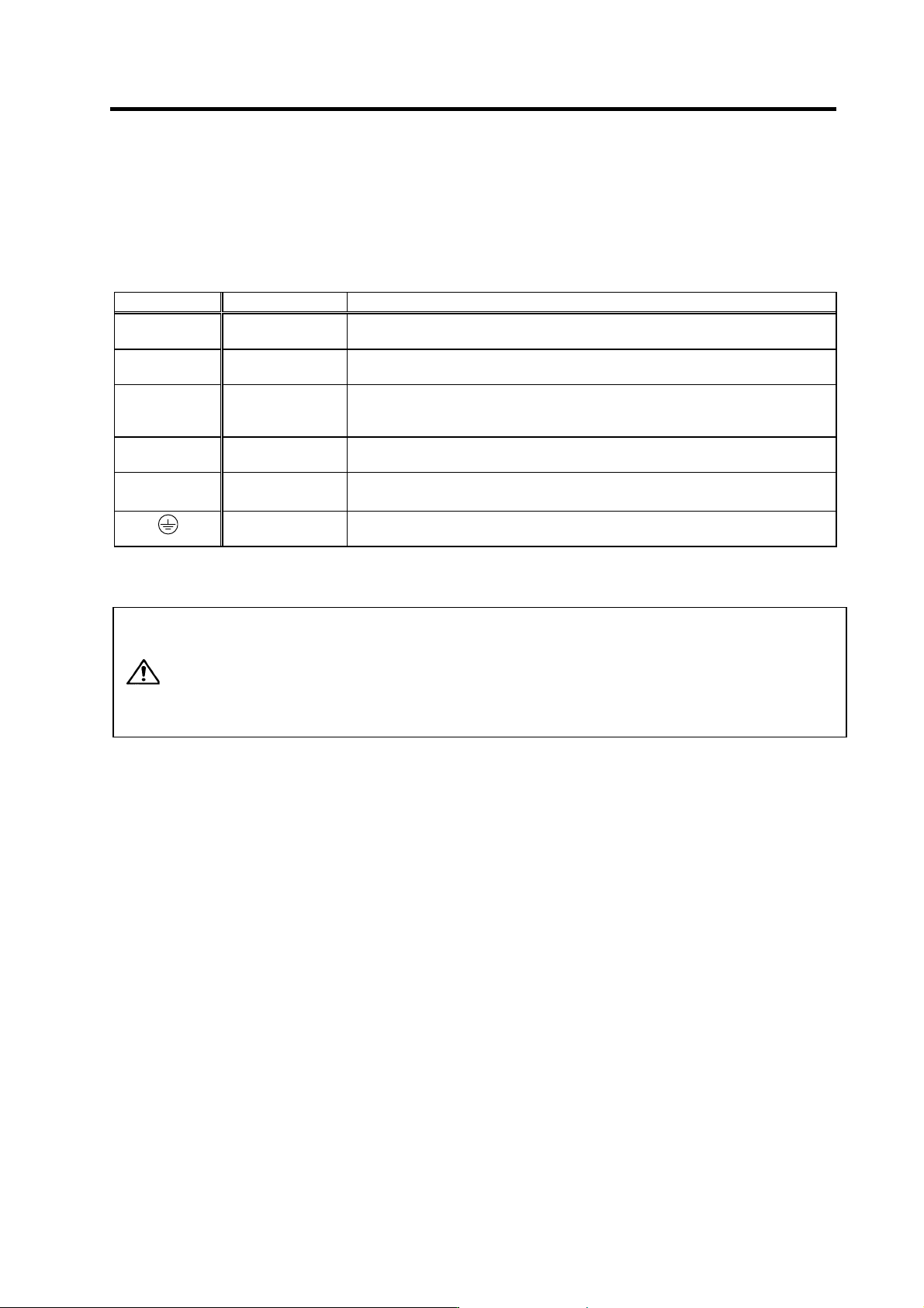
1. Always use one AC reactor per power supply unit. Failure to observe this
could lead to unit damage.
2. When sharing a breaker for several power supply units, of a short-circuit
fault occurs in a small capacity unit, the breaker could trip. This can be
hazardous, so do not share the breaker.
CAUTION
3. Be sure to use the breaker of proper capacity for each power supply unit.
2. Wiring and Connection
2 - 5
2-2-2 Connector pin assignment
CAUTION
Do not apply a voltage other than that specified in Instruction Manual on each
terminal. Failure to observe this item could lead to rupture or damage, etc.
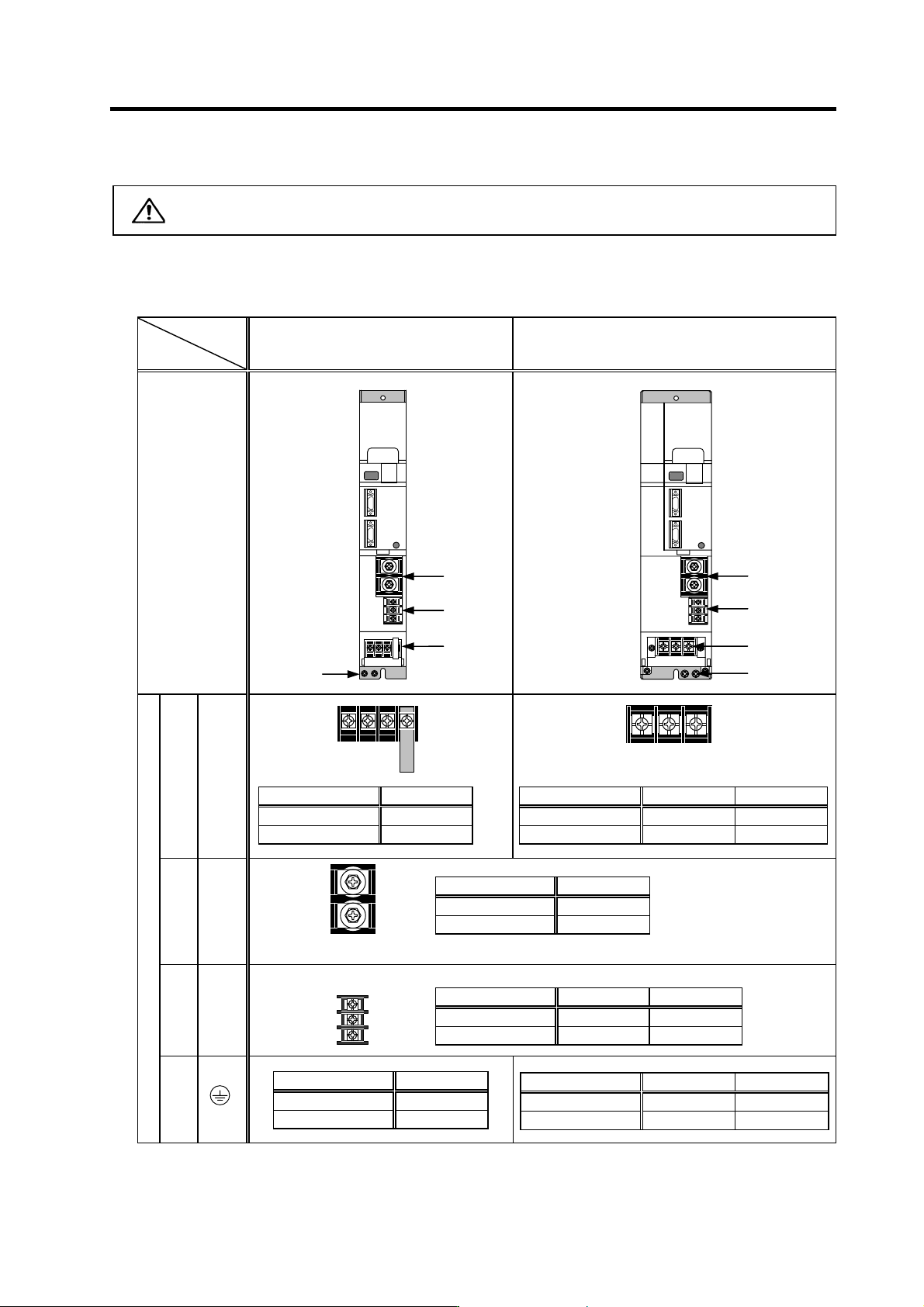
(1) Main circuit terminal block
Power supply unit
Unit
Terminal
MDS-C1-CV-37 to 75 MDS-C1-CV-110 to 370
Terminal
position
[1] TE1
Compatible unit CV-37 to 75
Screw size
M4
Tightening torque
1.6Nm
Compatible unit CV-110 to 185 CV-220 to 370
Screw size
M5 M8
Tightening torque
3.37Nm 13.2Nm
[2] TE2
Compatible unit CV-37 to 370
Screw size
M6
Tightening torque
5.0Nm
[3] TE3
Compatible unit CV-37 to 75 CV-110 to 370
Screw size M4 M4
Tightening torque 2.0Nm 1.6m
Terminal specification/Pin assignment
[4]
Compatible unit CV-37 to 75
Screw size M4
Tightening torque 2.0Nm
Compatible unit CV-110 to 185 CV-220 to 370
Screw size M5 M8
Tightening torque 3.37Nm 13.2Nm
[2]
[3]
[1]
[4]
[2]
[3]
[4]
[1]
U V W
L+
L-
L11
L21
MC1
U V W