bnp-b2365(eng)b.pdf - 第69页
2. Wiring and Connection 2 - 30 (3) Connecting the spindle end detector Refer to section (1) for connection with the spindle motor. U VW U V W CN5 S pindle motor CN6 Option cable: CNP6A Power cable MDS-C1-SP Max. 30m Opt…
2. Wiring and Connection
2 - 29
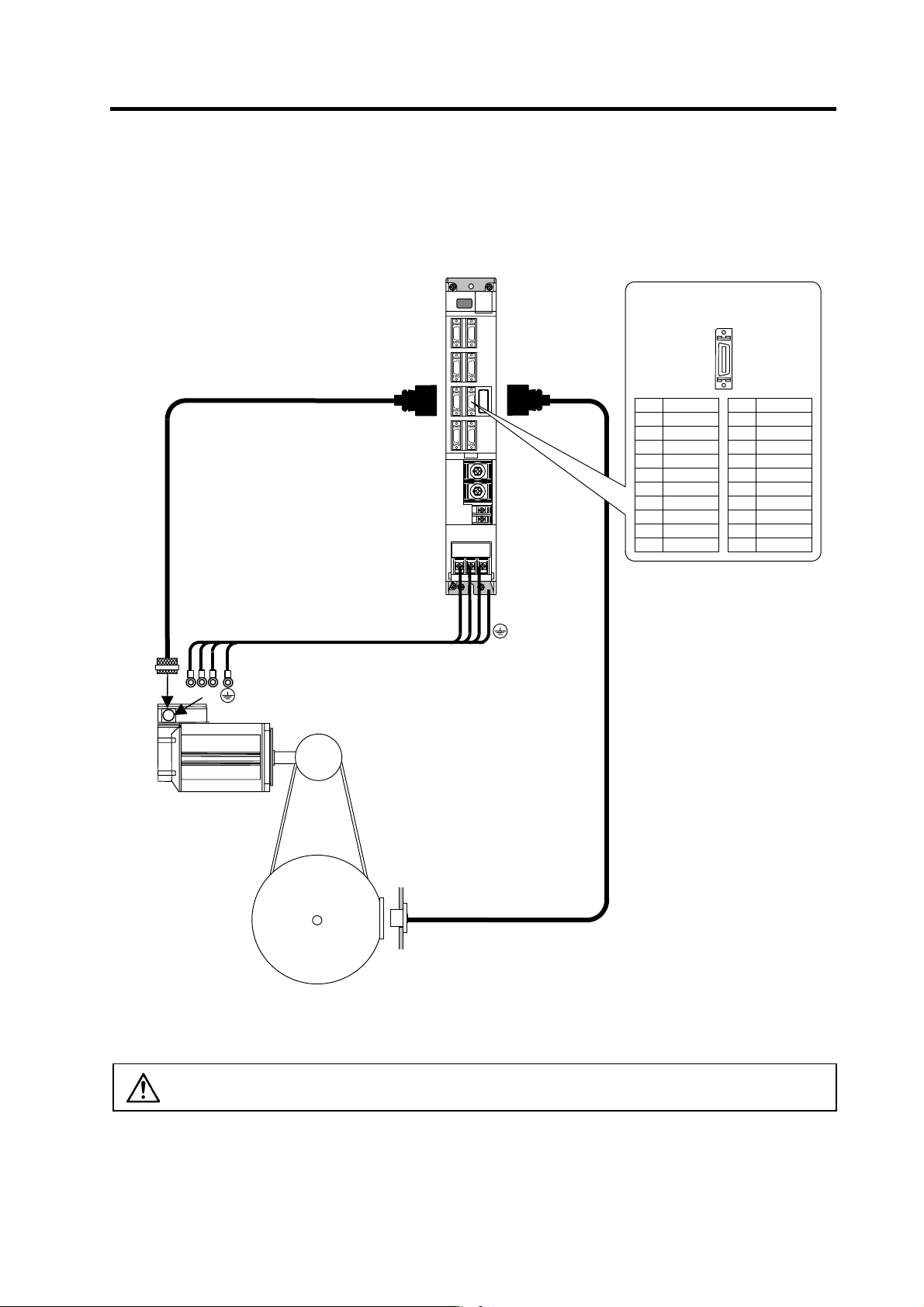
(2) Connecting the magnetic sensor
Refer to section (1) for connection with the spindle motor.
Name
P15(+15V)
MAG
LS
Pin
1
2
3
4
5
6
7
8
9
10
MDS-C1-SP
Option cable : CNP6M
Option cable : CNP5
U VW
U V W
CN5
Spindle motor
Magnetic sensor
Power cable
Max. 30m
CN6
Spindle
Pin No.
Detector connector : CN6
No.1
No.10
No.11
No.20
Name
LG
MAGR
LSR
Pin
11
12
13
14
15
16
17
18
19
20
CAUTION
The shield of spindle detector cable is not FG. Do not ground.
2. Wiring and Connection
2 - 30
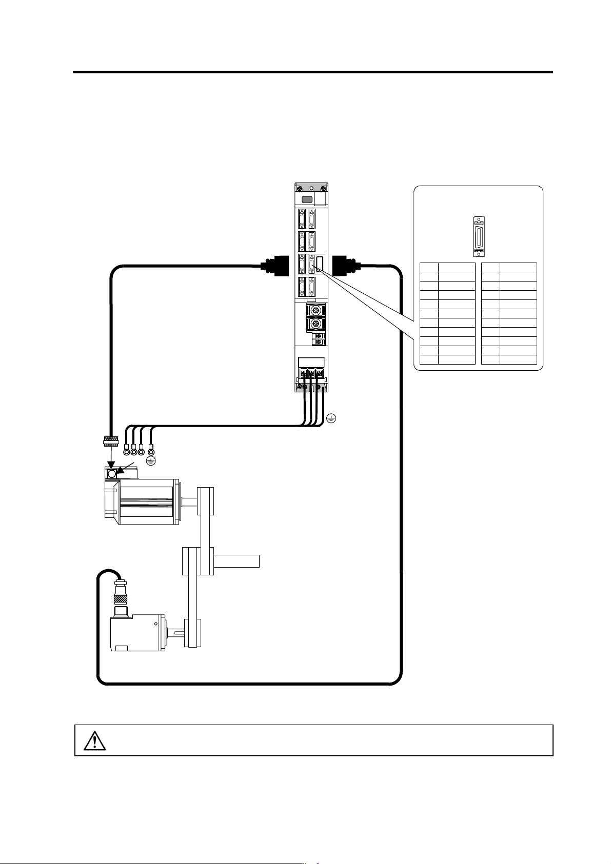
(3) Connecting the spindle end detector
Refer to section (1) for connection with the spindle motor.
U VW
U V W
CN5
Spindle motor
CN6
Option cable: CNP6A
Power cable
MDS-C1-SP
Max. 30m
Option cable : CNP5
Spindle end detector
Spindle
Pin No.
Detector connector : CN6
No.1
No.10
No.11
No.20
Name
LG
MA*
MB*
MZ*
LG
P5(+5V)
P5(+5V)
Pin
11
12
13
14
15
16
17
18
19
20
Name
LG
MA
MB
MZ
P5(+5V)
Pin
1
2
3
4
5
6
7
8
9
10
CAUTION
The shield of spindle detector cable is not FG. Do not ground.
2. Wiring and Connection
2 - 31
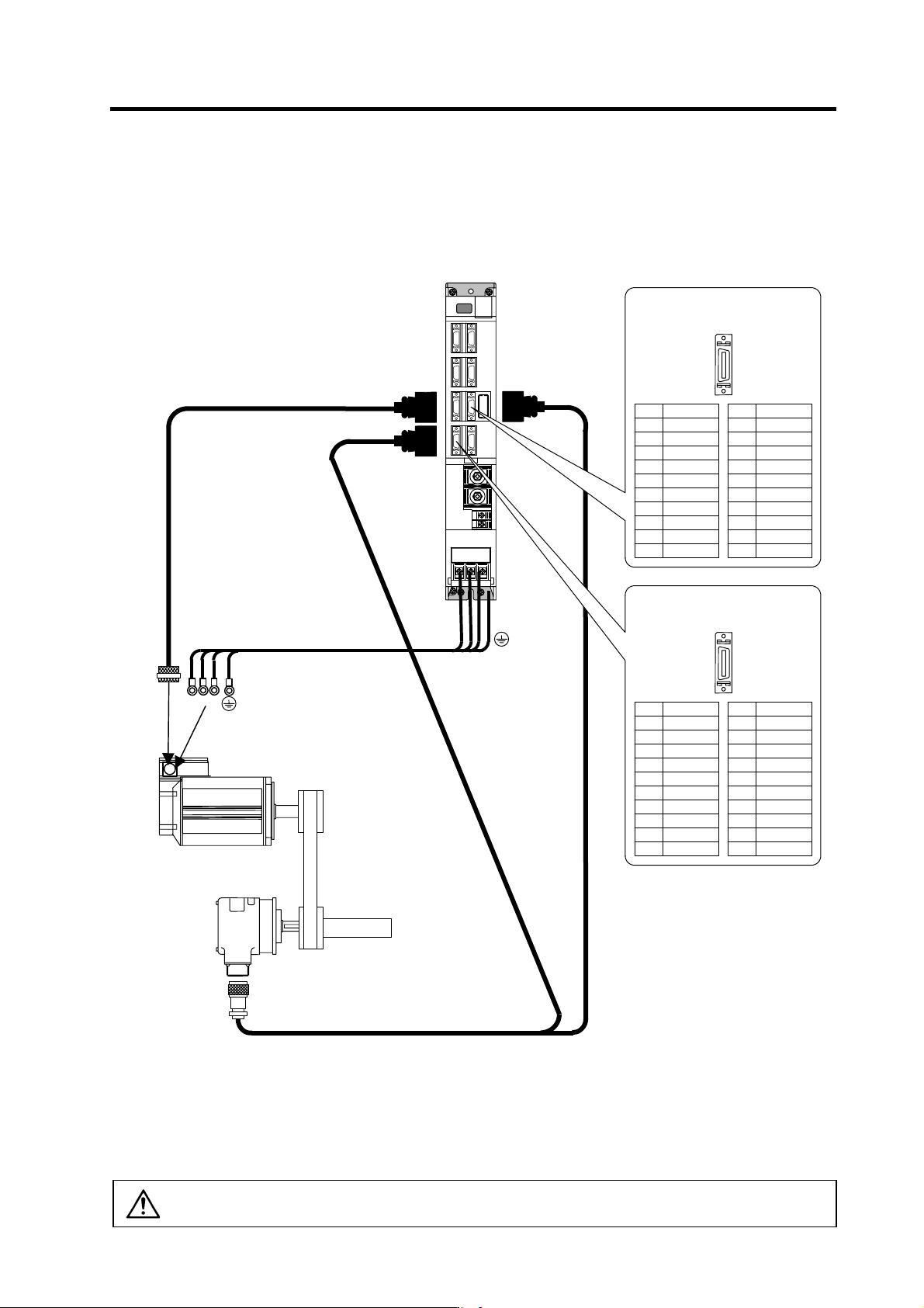
(4) Connecting the for C-axis detector
Refer to section (1) for connection with the spindle motor.
MDS-C1-SP
U VW
U V W
CN5
Spindle motor
C-axis detector
Power cable
CN7
Option cable : CNP7A
Option cable : CNP67A
CN6
Max. 30m
Option cable : CNP5
Spindle
Pin No.
Detector connector : CN6
No.1
No.10
No.11
No.20
Name
MA*
MB*
MZ*
Pin
11
12
13
14
15
16
17
18
19
20
Name
MA
MB
MZ
Pin
1
2
3
4
5
6
7
8
9
10
Pin No.
Detector connector : CN7
No.1
No.10
No.11
No.20
Name
LG
CA*
CB*
CZ*
LG
P5(+5V)
P5(+5V)
Pin
11
12
13
14
15
16
17
18
19
20
Name
LG
CA
CB
CZ
P5(+5V)
Pin
1
2
3
4
5
6
7
8
9
10
Supplement
1. The C-axis control function is connected to the CN7 connector.
2. When using both the C-axis control function and orient ation function, two cables (two-wire cable) are
connected from the detector.
3. The orientation signal connected to CN5 or CN6 can be connected to the NC with the differential
output from the CN8 connector.
CAUTION
The shield of spindle detector cable is not FG. Do not ground.