bnp-b2365(eng)b.pdf - 第317页
6. Troubleshooting 6 - 12 Alarm No. 17 A/D converter error An error was detected in the A/D converter for current FB detection. Investigation det ails In vestigation results Remedies SV SP 1 The error is always repeat ed…
6. Troubleshooting
6 - 11
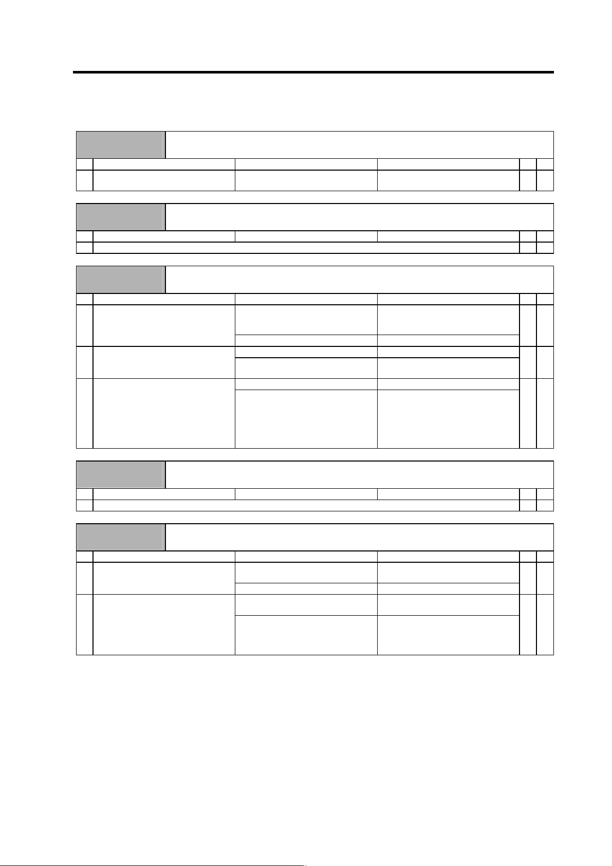
6-3-2 Troubleshooting for each alarm No.
Alarm No.
11
Axis selection error
The axis No. selection switch setting is incorrect.
Investigation details Investigation results Remedies SV SP
1 Check the setting of the axis
selection switch on the top of the unit.
The same axis No. is set for the L and
M axes.
Correctly set the axis No.
0 = No. 1 axis, 1 = No. 2 axis, ...
{
Alarm No.
12
Memory error 1
A CPU or internal memory error was detected during the self-check at power ON.
Investigation details Investigation results Remedies SV SP
1 Refer to "6-3-1 Troubleshooting at power ON".
{ {
Alarm No.
13
Software processing error 1
The software process was not completed within the specified time. (CPU1)
Investigation details Investigation results Remedies SV SP
The version was changed. Try replacing with the drive unit
containing the original software
version.
1 Check whether the servo software
version was changed recently.
The version was not changed. Investigate item 2.
{ {
The error is always repeated. Replace the drive unit. 2 Check the repeatability.
The state returns to normal once, but
occurs sometimes thereafter.
Investigate item 3.
{ {
No abnormality is found in particular. Replace the drive unit. 3 Check if there is any abnormality in
the unit's ambient environment.
(Ex. Ambient temperature, noise,
grounding)
An abnormality was found in the
ambient environment.
Take remedies according to the
causes of the abnormality.
Ex. High temperature:
Check the cooling fan.
Incomplete grounding:
Additionally ground.
{ {
Alarm No.
14
Software processing error 2
The software process was not completed within the specified time. (CPU2)
Investigation details Investigation results Remedies SV SP
1 Carry out the items for alarm No. 13.
{ {
Alarm No.
16
Magnetic pole position detection error
Creation of the initial magnetic pole, required for motor control, was not completed.
Investigation details Investigation results Remedies SV SP
It was replaced. Carry out automatic adjustment of the
PLG Z-phase.
1 Was the spindle drive unit replaced?
It was not replaced. Investigate item 2.
{
SP205 = 0 Carry out automatic adjustment of the
PLG Z-phase.
2 Check the spindle parameters.
SP205 = 1 Set SP205 to 0, and turn the NC
power ON again. Then, carry out
automatic adjustment of the PLG
Z-phase.
{
6. Troubleshooting
6 - 12
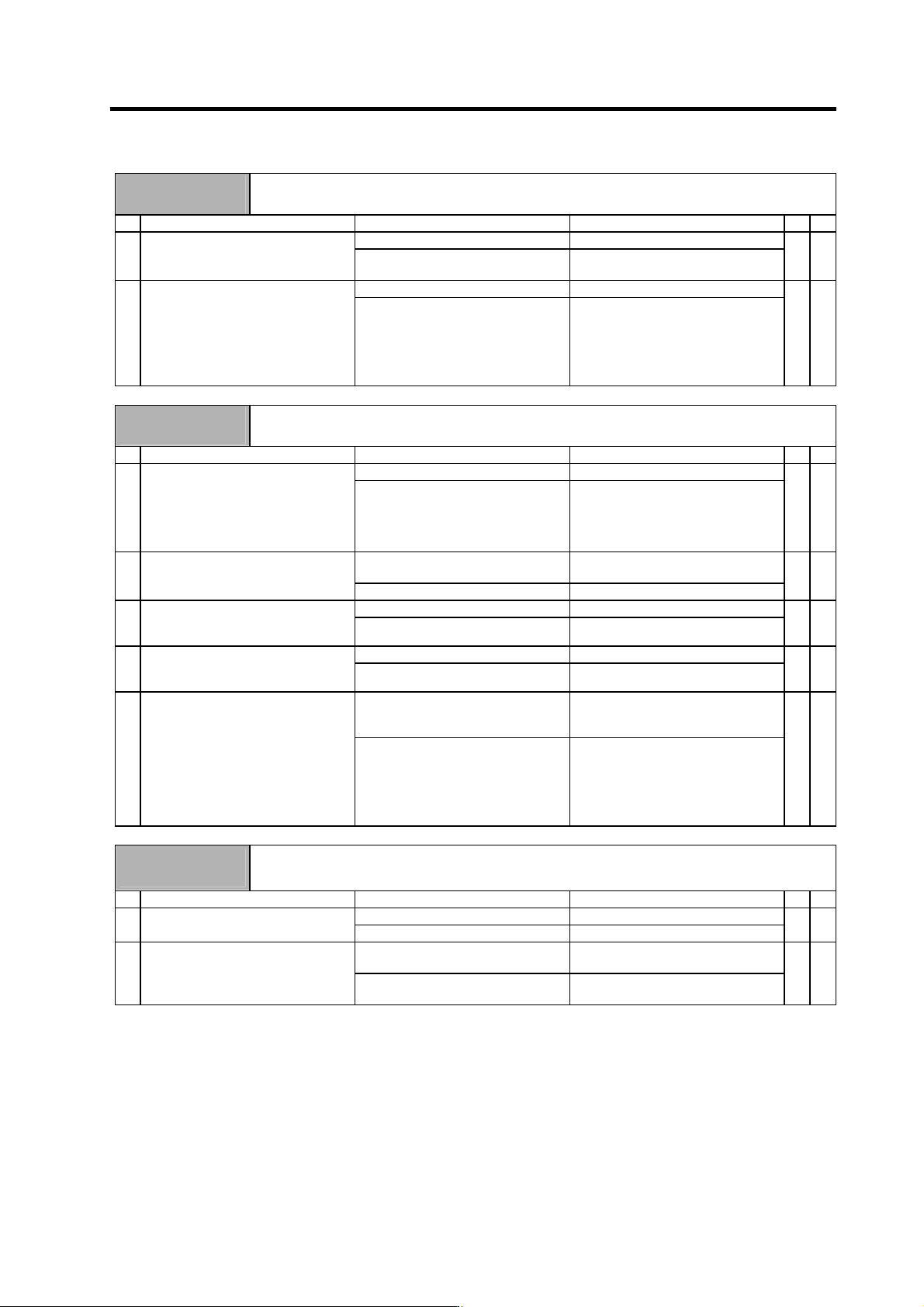
Alarm No.
17
A/D converter error
An error was detected in the A/D converter for current FB detection.
Investigation details Investigation results Remedies SV SP
1 The error is always repeated. Replace the drive unit.
Check the repeatability.
The state returns to normal once, but
occurs sometimes thereafter.
Investigate item 2.
{ {
2 No abnormality is found in particular. Replace the drive unit.
Check if there is any abnormality in
the unit's ambient environment.
(Ex. Ambient temperature, noise,
grounding)
An abnormality was found in the
ambient environment.
Take remedies according to the
causes of the abnormality.
Ex. High temperature:
Check the cooling fan.
Incomplete grounding:
Additionally ground.
{ {
Alarm No.
18
Motor side detector, initial communication error
Initial communication with the motor end detector was not possible.
Investigation details Investigation results Remedies SV SP
The value is not set correctly. Correctly set SV025. 1 Check the servo parameter (SV025)
setting value.
OSE104: 0, OSA104: 1
Are all other set to 2?
(Excluding slave axis for
synchronous control)
The value is set correctly. Investigate item 2.
{
The connector is disconnected (or
loose).
Correctly install. 2 Check whether the drive unit
connectors (CN2) or detector
connectors are disconnected.
The connector is not disconnected. Investigate item 3.
{
There is a connection fault. Replace the detector cable. 3 Turn the power OFF, and check the
detector cable connection with a
tester.
The connection is normal. Investigate item 4.
{
The alarm is on the drive unit side. Replace the drive unit. 4 Connect to another normal axis drive
unit, and check whether the fault is
on the drive unit side or detector side.
The alarm is on the detector side. Investigate item 5.
{
No abnormality is found in particular. Replace the detector.
(With the absolute position system,
the zero point must be established.)
5 Check if there is any abnormality in
the detector's ambient environment.
(Ex. Ambient temperature, noise,
grounding)
An abnormality was found in the
ambient environment.
Take remedies according to the
causes of the abnormality.
Ex. High temperature:
Check the cooling fan.
Incomplete grounding:
Additionally ground.
{
Alarm No.
19
Synchronous control/detector communication error
Initial communication with the master axis motor end detector was not possible when the closed current
command synchronous control was set. Or, the communication was cut off.
Investigation details Investigation results Remedies SV SP
The connector is disconnected. Correctly connect. 1 Check whether the MDS-B-SD unit
CN2B connector is disconnected.
The connector is not disconnected. Investigate item 2.
{
The cable is disconnected or
incorrectly connected.
Replace the cable. 2 Check the continuity of the cable
between the MDS-B-SD unit CN2B
and the slave side drive unit CN3.
There is no abnormality in particular. Try replacing the drive unit or
MDS-B-SD unit.
{
6. Troubleshooting
6 - 13
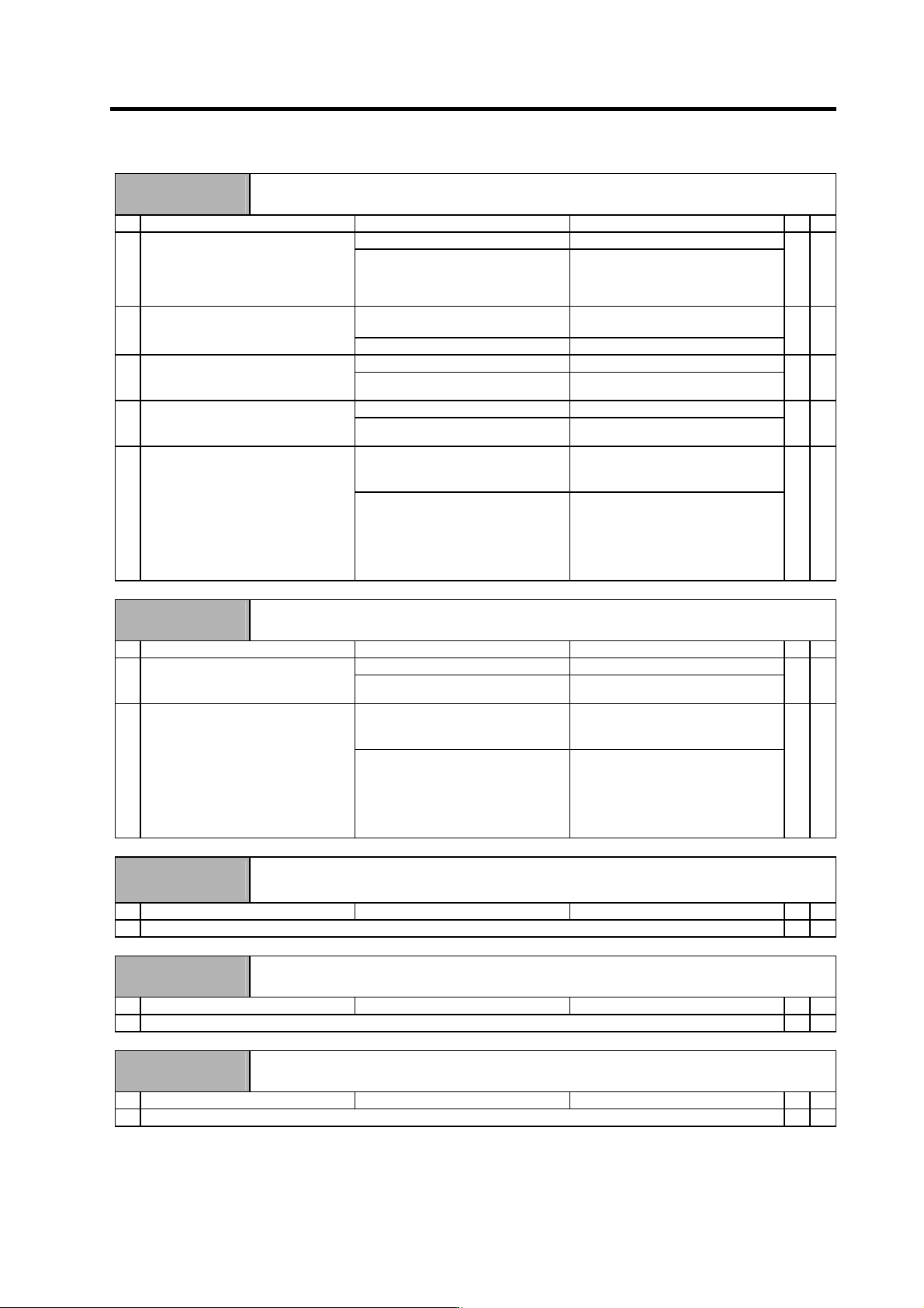
Alarm No.
1A
Machine side detector, initial communication error
Initial communication with the linear scale or ball screw end detector was not possible.
Investigation details Investigation results Remedies SV SP
The value is not set correctly. Correctly set SV025. 1 Check the servo parameter
(SV025.pen) setting value.
Are the serial communication
parameters set for the pulse-type
detector?
The value is set correctly. Investigate item 2.
{
The connector is disconnected (or
loose).
Correctly install. 2 Check whether the drive unit
connectors (CN3) or detector
connectors are disconnected.
The connector is not disconnected. Investigate item 3.
{
There is a connection fault. Replace the detector cable. 3 Turn the power OFF, and check the
detector cable connection with a
tester.
The connection is normal. Investigate item 4.
{
The alarm is on the drive unit side. Replace the drive unit. 4 Connect to another normal axis drive
unit, and check whether the fault is
on the drive unit side or detector side.
The alarm is on the detector side. Investigate item 5.
{
No abnormality is found in particular. Replace the detector.
(With the absolute position system,
the zero point must be established.)
5 Check if there is any abnormality in
the detector's ambient environment.
(Ex. Ambient temperature, noise,
grounding)
An abnormality was found in the
ambient environment.
Take remedies according to the
causes of the abnormality.
Ex. High temperature:
Check the cooling fan.
Incomplete grounding:
Additionally ground.
{
Alarm No.
1B
Machine side detector, CPU error 1
A CPU initial error was detected with the linear scale or ball screw end detector.
Investigation details Investigation results Remedies SV SP
The alarm is on the drive unit side. Replace the drive unit. 1 Connect to another normal axis drive
unit, and check whether the fault is
on the drive unit side or scale side.
The alarm is on the detector side. Investigate item 2.
{
No abnormality is found in particular. Replace the detector.
(With the absolute position system,
the zero point must be established.)
2 Check if there is any abnormality in
the detector's ambient environment.
(Ex. Ambient temperature, noise,
grounding)
An abnormality was found in the
ambient environment.
Take remedies according to the
causes of the abnormality.
Ex. High temperature:
Check the cooling fan.
Incomplete grounding:
Additionally ground.
{
Alarm No.
1C
Machine side detector, EEPROM/LED abnormality
An error was detected in the data stored in the memory by the linear scale. Or, LED deterioration was
detected with the linear scale.
Investigation details Investigation results Remedies SV SP
1 Check the alarm No. "1B" items.
{
Alarm No.
1D
Machine side detector, data error
A data error was detected with the linear scale or ball screw end detector.
Investigation details Investigation results Remedies SV SP
1 Check the alarm No. "1B" items.
{
Alarm No.
1E
Machine side detector, memory error
An internal memory error was detected with the linear scale.
Investigation details Investigation results Remedies SV SP
1 Check the alarm No. "1B" items.
{