bnp-b2365(eng)b.pdf - 第66页
2. Wiring and Connection 2 - 27 (4-2) Connection for full-closed synchronous control (w hen using MDS-C1-V2 drive unit and analog output linear scale) Master axis Slave axis Detector cable CNV12 Linear scale MDS-C1-V2 De…
2. Wiring and Connection
2 - 26
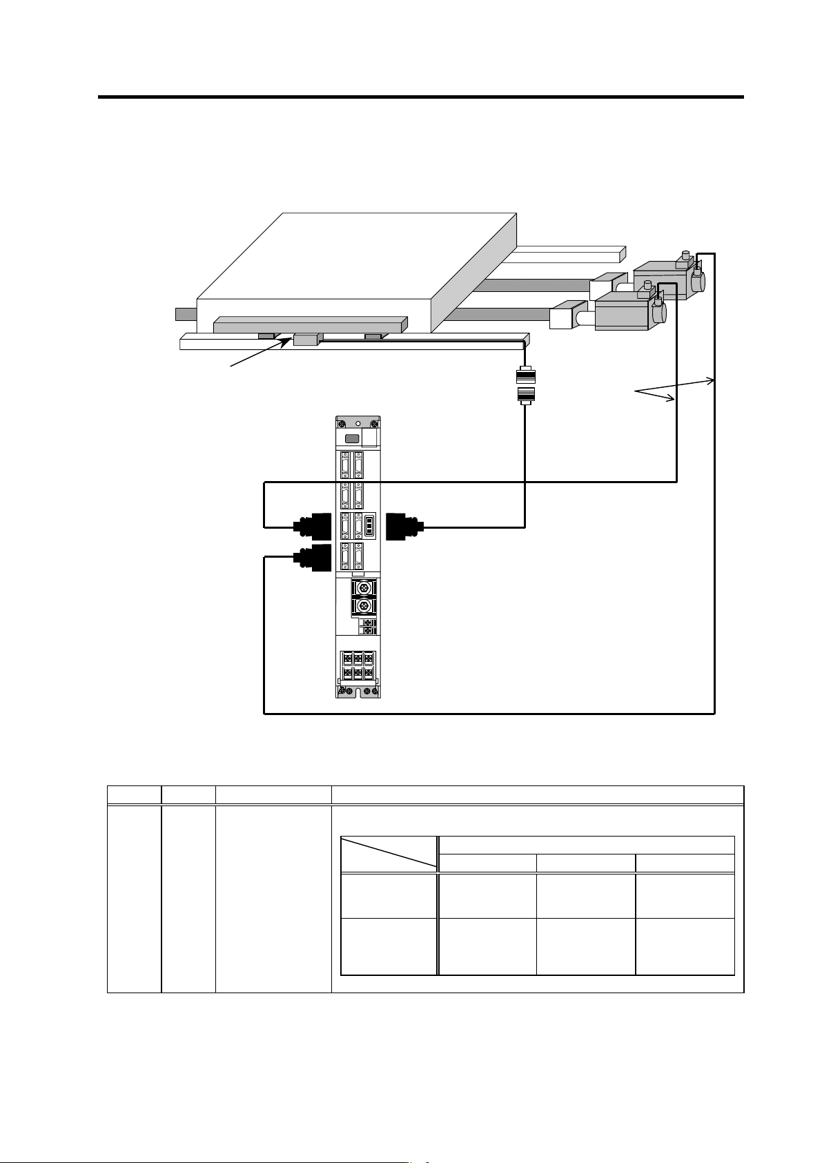
(4-1) Connection for full-closed synchronous control
(when using MDS-C1-V2 drive unit and serial output linear scale)
Master axis
Slave axis
Detector cable
CNV12
Linear scale
MDS-C1-V2
CN2M
CN2L
CN3L
Parameter settings
No. Abbrev. Parameter name Description
Set the detector type. The value determined for each motor type is input to “xx” in the
following table.
Motor end detector type
OSE104 OSA104 OSE105/OSA105
Speed command
synchronous
control
Master axis =A0xx
Slave axis =D0xx
Master axis =A1xx
Slave axis =D1xx
Master axis =A2xx
Slave axis =D2xx
Current
command
synchronous
control
Master axis =A0xx
Slave axis =DExx
Master axis =A1xx
Slave axis =DExx
Master axis =A2xx
Slave axis =DExx
SV025 MTYP Motor/detector type
2. Wiring and Connection
2 - 27
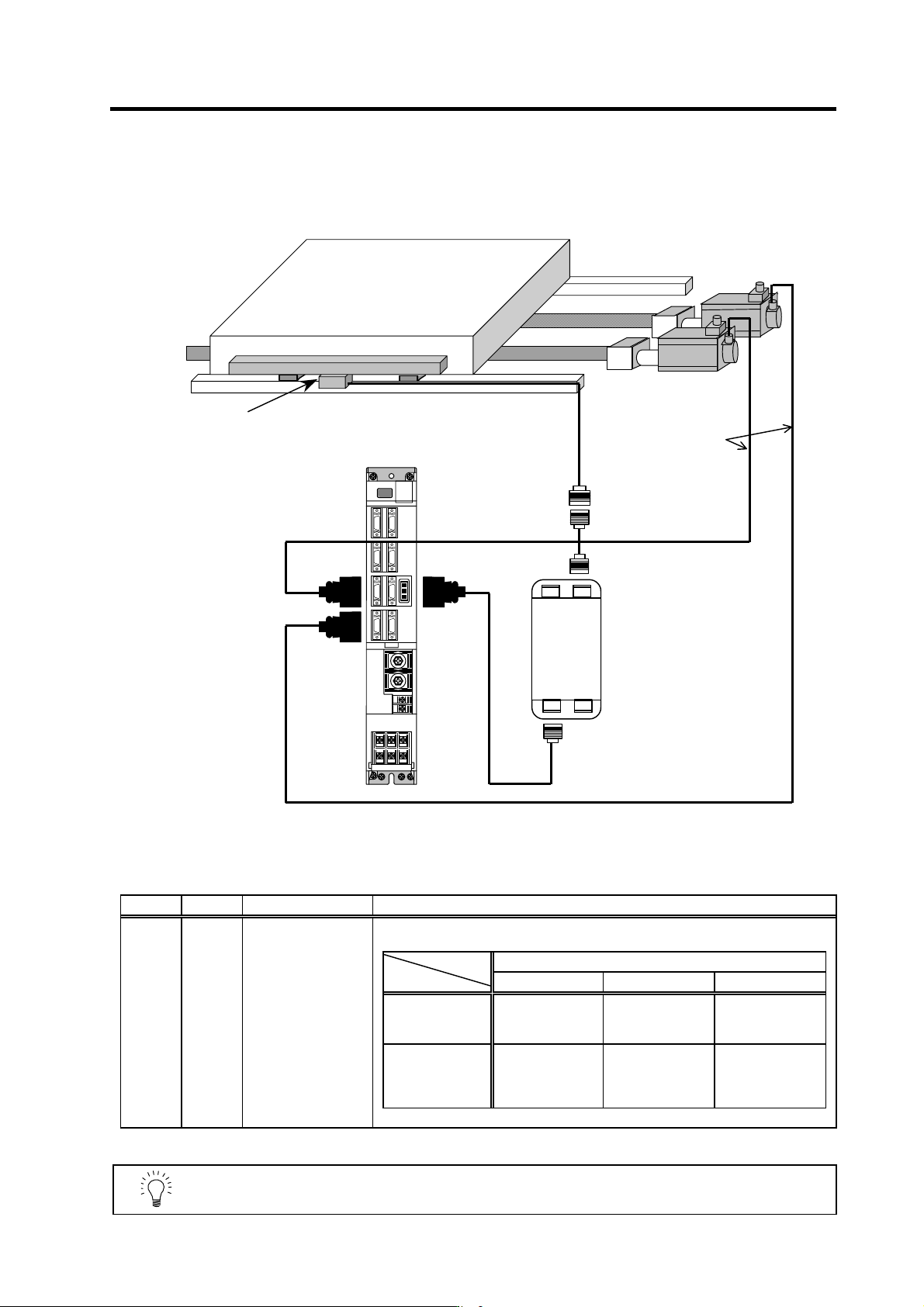
(4-2) Connection for full-closed synchronous control
(when using MDS-C1-V2 drive unit and analog output linear scale)
Master axis
Slave axis
Detector cable
CNV12
Linear scale
MDS-C1-V2
Detector
Converter
unit
MDS-B-HR
CON1CON2
CON3CON4
CN2L
CN2M
CN3L
Parameter settings
No. Abbrev. Parameter name Description
Set the detector type. The value determined for each motor type is input to “xx” in the
following table.
Motor end detector type
OSE104 OSA104/OSA105 OSE105
Speed command
synchronous
control
Master axis =A0xx
Slave axis =D0xx
Not compatible
Master axis =A2xx
Slave axis =D2xx
Current
command
synchronous
control
Master axis =A0xx
Slave axis =DExx
Not compatible
Master axis =A2xx
Slave axis =DExx
SV025 MTYP Motor/detector type
POINT
In a system in which MDS-B-HR is used, this connection is compatible only with
incremental control.
2. Wiring and Connection
2 - 28
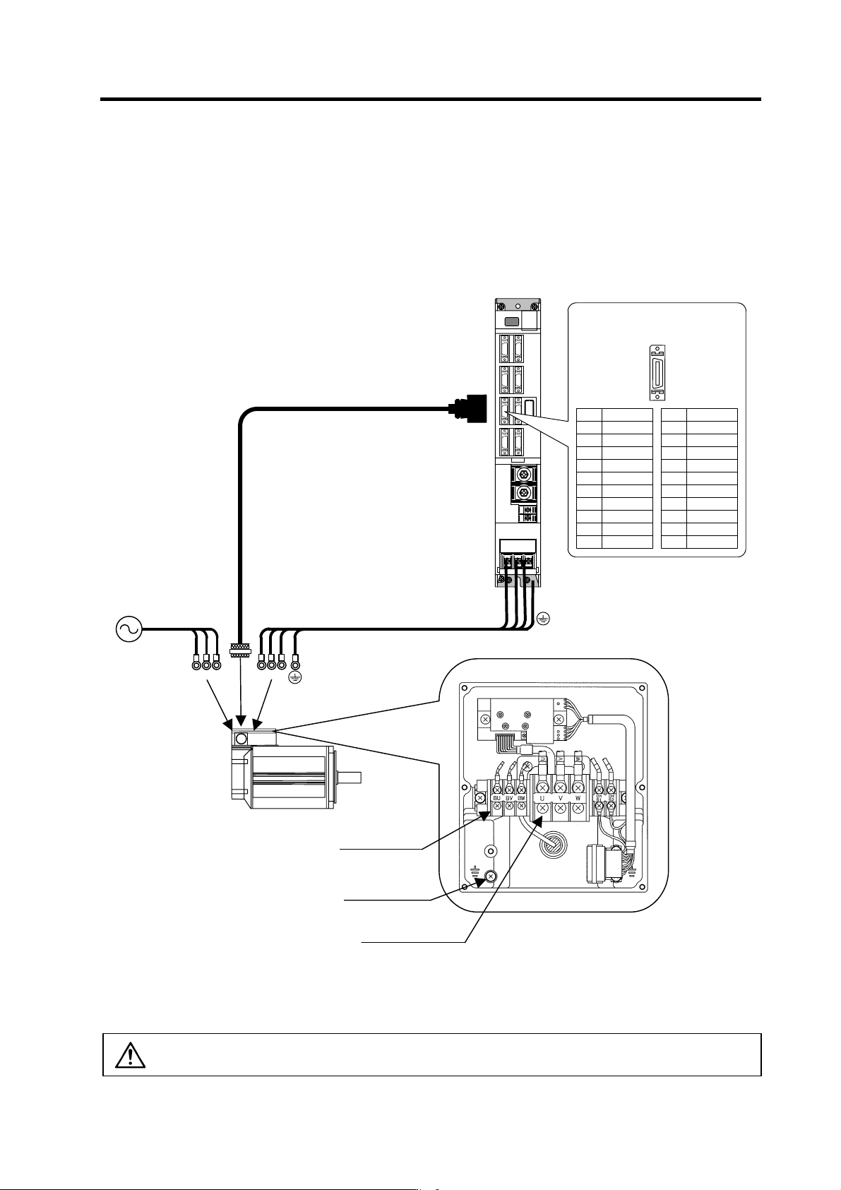
2-4-4 Connection of the spindle motor
Refer to each motor specifications for details on the motor side connection destination, specifications
and outline, and for the spindle PLG detector specifications.
(1) Connecting the motor built-in PLG
U VW
Max. 30m
U V W
CN5
Spindle motor
MDS-C1-SP
Power cable
Option cable : CNP5
BU
BW
BV
Cooling fan terminal
block (BU,BV,BW)
Grounding terminal
Motor power terminal
block (U,V,W)
Example for 3-phase cooling fan
power supply
(Note) Either a single-phase or 3-phase power supply is used for the cooling fan.
Refer to the Spindle Motor Specifications for details.
Pin No.
Detector connector : CN5
No.1
No.10
No.11
No.20
Name
RG
N15(-15V)
RA
RB
Pin
11
12
13
14
15
16
17
18
19
20
Name
LG
MOH
P15(+15V)
PA
PB
PZ
Pin
1
2
3
4
5
6
7
8
9
10
CAUTION
The shield of spindle detector cable is not FG. Do not ground.