bnp-b2365(eng)b.pdf - 第361页
Appendix 1. Cable and Connector Specifications A1 - 5 Back shell Connector for conduit Flexible conduit Cable Connecto r Model DDK Nippon Flex Appli- cation Applicable motors Connector/back shell (straight) Connector/bac…
Appendix 1. Cable and Connector Specifications
A1 - 4
Appendix 1-1-2 Flexible conduits
Basically, splash proofing can be ensured if cab-tire cable and connectors with IP65 or higher
specifications are used. However, to further improve the oil resistance (chemical resistance to oil),
weather resistance (resistance to the environment when used outdoors, etc.), durability, tensile strength,
flattening strength, etc., run the cable through a flexible conduit when wiring.
The following shows an example of a flexible conduit. Contact the connector maker for more
information.
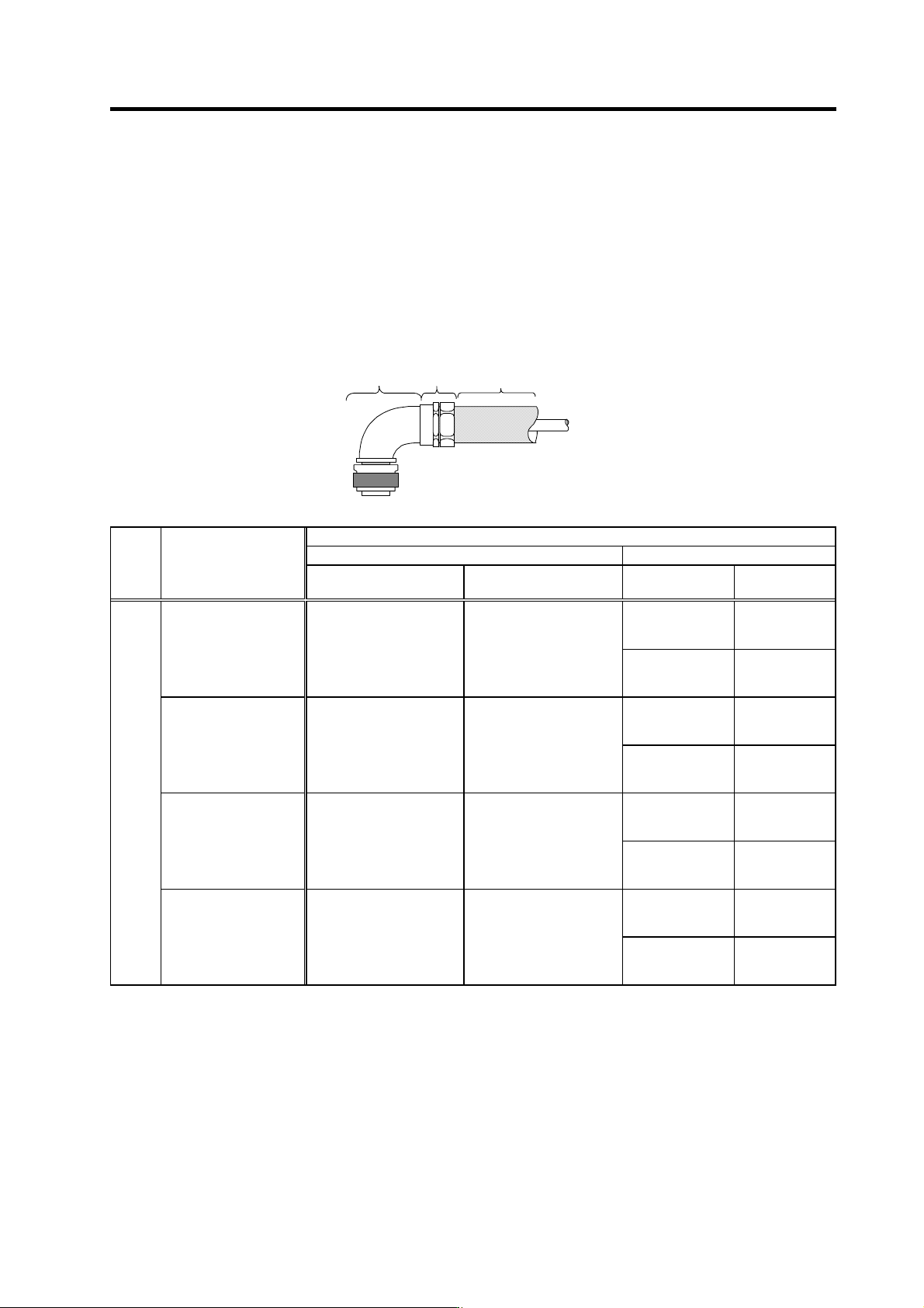
(1) Method for connecting to a connector with back shell
Connector with
back shell
Connector
for conduit
Flexible conduit
Cable
Model
DDK Nippon Flex
Appli-
cation
Applicable motors
Connector (straight) Connector (angle)
Connector for
conduit
Flexible
conduit
RCC-103CA18
VF-03
(Min. inside
diameter: 10.6)
For
power
HA053N, HA13N
HA23N, HA33N
CE05-6A18-12SD-B-BSS CE05-8A18-12SD-B-BAS
RCC-104CA18
VF-04
(Min. inside
diameter: 14)
RCC-104CA2022
VF-04
(Min. inside
diameter: 14)
HC52, HC102, HC152
HC53, HC103, HC153
HC103R, HC153R,
HC203R
CE05-6A22-23SD-B-BSS CE05-8A22-23SD-B-BAS
RCC-106CA2022
VF-06
(Min. inside
diameter: 19)
RCC-106CA2428
VF-06
(Min. inside
diameter: 19)
HC202, HC352, HC452
HC203, HC353
HC353R, HC503R
CE05-6A24-10SD-B-BSS CE05-8A24-10SD-B-BAS
RCC-108CA2428
VF-08
(Min. inside
diameter: 24.4)
RCC108CA32
VF-08
(Min. inside
diameter: 24.4)
HC702, HC902
HC453, HC703
CE05-6A32-17SD-B-BSS CE05-8A32-17SD-B-BAS
RCC110CA32
VF-10
(Min. inside
diameter: 33.0)
(Note) None of the parts in this table can be ordered from Mitsubishi Electric Corp.
Appendix 1. Cable and Connector Specifications
A1 - 5
Back shell
Connector
for conduit
Flexible conduit
Cable
Connecto
r
Model
DDK Nippon Flex
Appli-
cation
Applicable motors
Connector/back
shell (straight)
Connector/back
shell (angle)
Connector for
conduit
Flexible conduit
For
brake
HA053NB to HA33NB
HC202B to HC902B
HC203B to HC703B
Select according to section "(2) Method for connecting to the connector main body".
RCC-104CA2022
VF-04
(Min. Inside diameter: 14)
For
detector
HA053N to HA33N
HC52 to HC902, HC53 to HC703
HC103R to HC503R
HA-LF11K2-S8, HA-LF15K2-S8
Connector
MS3106A22-14S
(D190)
Back shell
CE02-22BS-S
Connector
MS3106A22-14S
(D190)
Back shell
CE-22BA-S
RCC-106CA2022
VF-06
(Min. Inside diameter: 19)
(Note) None of the parts in this table can be ordered from Mitsubishi Electric Corp.
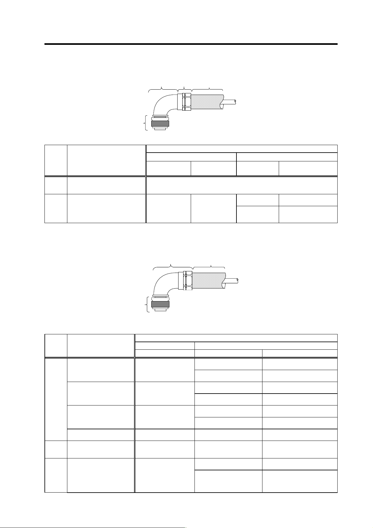
(2) Method for connecting to the connector main body
Connector for conduit
Flexible conduit
Cable
Connector
Model
DDK DAIWA DENGYO
Appli-
cation
Applicable motors
Connector (straight) Connector for conduit Flexible conduit
MSA-12-18
MAA-12-18
(Straight)
(Angle)
FCV12
(Min. inside diameter: 12.3)
For
power
HA053N, HA13N
HA23N, HA33N
CE05-6A18-12SD-B
MSA-16-18
MAA-16-18
(Straight)
(Angle)
FCV16
(Min. inside diameter: 15.8)
MSA-16-22
MAA-16-22
(Straight)
(Angle)
FCV16
(Min. inside diameter: 15.8)
HC52, HC102, HC152
HC53, HC103, HC153
HC103R, HC153R, HC203R
CE05-6A22-23SD-B
MSA-22-22
MAA-22-22
(Straight)
(Angle)
FCV22
(Min. inside diameter: 20.8)
MSA-22-24
MAA-22-24
(Straight)
(Angle)
FCV22
(Min. inside diameter: 20.8)
HC202, HC352, HC452
HC203, HC353
HC353R, HC503R
CE05-6A24-10SD-B
MSA-28-24
MAA-28-24
(Straight)
(Angle)
FCV28
(Min. inside diameter: 26.4)
HC702, HC902
HC453, HC703
CE05-6A32-17SD-B Please contact to a maker.
FCV36
(Min. inside diameter: 35.0)
For
brake
HA053NB to HA33NB
HC202B to HC902B
HC203B to HC703B
MS3106A10SL-4S (D190)
MSA-10-10
MAA-10-10
(Straight)
(Angle)
FCV10
(Min. inside diameter: 10.0)
MSA-16-22
MAA-16-22
(Straight)
(Angle)
FCV16
(Min. inside diameter: 15.8)
For
detector
HA053N to HA33N
HC52 to HC902,
HC53 to HC703
HC103R to HC503R
HA-LF11K2-S8,
HA-LF15K2-S8
MS3106A22-14S (D190)
MSA-22-22
MAA-22-22
(Straight)
(Angle)
FCV22
(Min. inside diameter: 20.8)
(Note) None of the parts in this table can be ordered from Mitsubishi Electric Corp.
Appendix 1. Cable and Connector Specifications
A1 - 6
Appendix 1-2 Cable connection diagram
CAUTION
1. Do not mistake the connection when manufacturing the detector cable.
Failure to observe this could lead to faults, runaway or fires.
2. Do not connect anything to pins unless otherwise particularly specified when
manufacturing a cable. (Leave OPEN)
3. Contact Mitsubishi when manufacturing a cable longer than 30m.
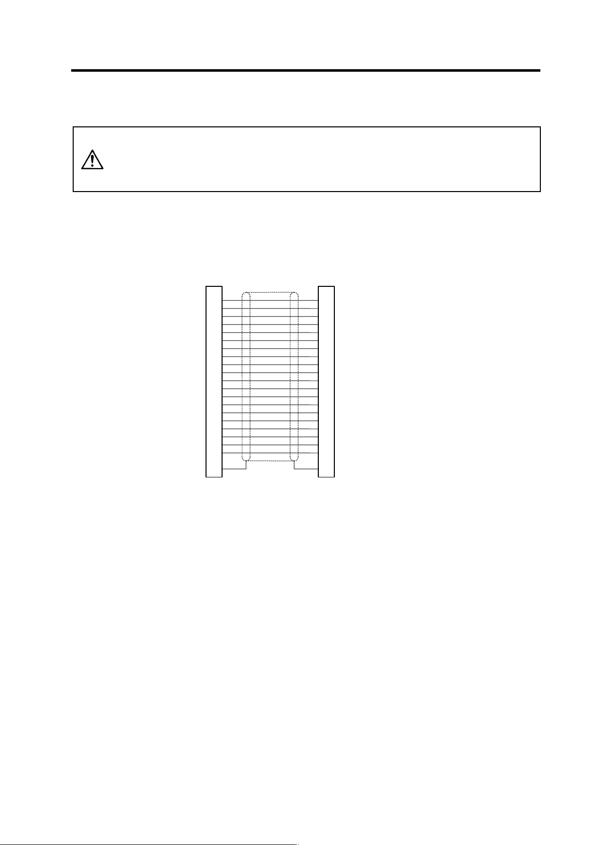
(1) NC bus cable
<SH21 cable connection diagram>
Drive unit side connector
Connector: 10120-3000VE
Shell kit: 10320-52F0-008
Drive unit side connector
Connector: 10120-3000VE
Shell kit: 10320-52F0-008
1
11
2
12
3
13
4
14
5
15
6
16
7
17
8
18
9
19
10
20
PE
1
11
2
12
3
13
4
14
5
15
6
16
7
17
8
18
9
19
10
20
PE
FG