bnp-b2365(eng)b.pdf - 第140页
3. Setup 3 - 53 Standard specifications No. Abbrev. Parameter name Explanation Setting range (Unit) F E D C B A 98765 4 3 2 10 mpt mp abs vdir fdir s pw v seqh dfbx bit Meaning w hen “0” is set Meaning when “1” is set 0 …

3. Setup
3 - 52
Standard specifications
No. Abbrev. Parameter name Explanation
Setting
range (Unit)
SV013 ILMT Current limit value
Set the normal current (torque) limit value. (Limit values for both + and -
direction.)
When the value is “500” (a standard setting), the maximum torque is
determined by the specification of the motor.
0 to 999
(Stall
[rated]
current %)
SV014 ILMTsp
Current limit value in
special control
Set the current (torque) limit value in a special control (initial absolute
position setting, stopper control, etc). (Limit values for both of the + and -
directions.)
Set to “500” when not using.
0 to 999
(Stall
[rated]
current %)
SV015 FFC
Acceleration rate
feed forward gain
When a relative error in the synchronous control is large, apply this
parameter to the axis that is delaying. The standard setting value is “0”.
For the SHG control, set to “100”.
To adjust a relative error in acceleration/deceleration, increase the value by
50 to 100 at a time.
0 to 999
(%)
Set this when the protrusion (that occurs due to the non-sensitive band by
friction, torsion, backlash, etc) at quadrant change is too large.
This compensates the torque at quadrant change.
This is valid only when the lost motion compensation (SV027 (SSF1.lmc))
is selected.
Type 1: When SV027 (SSF1)/bit9, 8 (lmc)=01
Set the compensation amount based on the motor torque before the
quadrant change.
The standard setting is “100”. Setting to “0” means the compensation
amount is zero.
Normally, use Type 2.
-1 to 200
(%)
Type 2: When SV027 (SSF1)/bit9, 8 (lmc)=10
Set the compensation amount based on the stall (rated) current of the
motor.
The standard setting is double of the friction torque. Setting to “0”
means the compensation amount is zero.
-1 to 200
(Stall
[rated]
current %)
SV016 LMC1
Lost motion
compensation 1
When you wish different compensation amount depending on the direction
When SV041 (LMC2) is “0”, compensate with the value of SV016
(LMC1) in both of the + and -directions.
If you wish to change the compensation amount depending on the
command direction, set this and SV041 (LMC2). (SV016: + direction,
SV041: - direction. However, the directions may be opposite
depending on other settings.)
When “-1” is set, the compensation won’t be performed in the direction of
the command.
Parameters with an asterisk * in the abbreviation, such as PC1*, are validated with the NC power turned ON again.
3. Setup
3 - 53
Standard specifications
No. Abbrev. Parameter name Explanation
Setting
range (Unit)
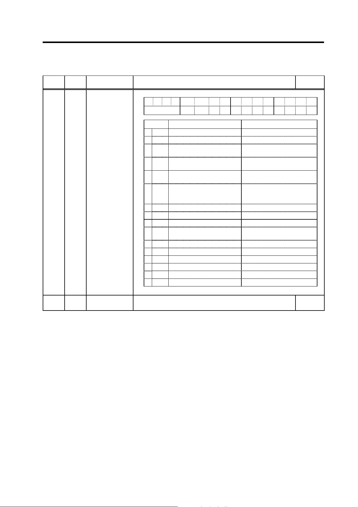
FEDCB A 98765 4 3 2 10
mpt mp abs vdir fdir
s
pw
v
seqh dfbx
bit Meaning when “0” is set Meaning when “1” is set
0
1 dfbx Dual feedback control stop Dual feedback control start
2 seqh
Normal ready ON/servo ON time High-speed ready ON/servo ON
time
3spwv
Normal mode High-gain servo synchronization
mode
4fdir
Position feedback forward
polarity
Position feedback reverse polarity
5vdir
Standard setting HA motor (4 pole motor)
Detector installation position 90
degrees (B, D)
6
7 abs Incremental control Absolute position control
8 mp MP scale 360P (2mm pitch) MP scale 720P (1mm pitch)
9mpt
MP scale ABS detection NC
control
MP scale ABS detection
automatic (Standard swetting)
A
B
C
D
E
F
SV017 SPEC*
Servo specification
selection
(Note) Set to “0” for bits with no particular description.
SV018 PIT* Ball screw pitch
Set the ball screw pitch. Set to “360” for the rotary axis.
1 to 32767
(mm/rev)
Parameters with an asterisk * in the abbreviation, such as PC1*, are validated with the NC power turned ON again.
3. Setup
3 - 54
Standard specifications
No. Abbrev. Parameter name Explanation
Setting range
(Unit)
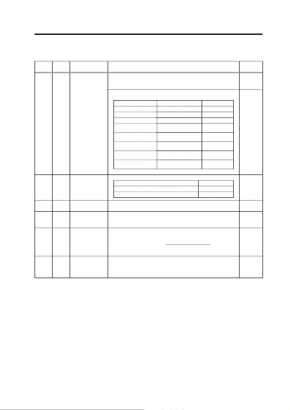
In the case of the semi-closed loop control
Set the same value as SV020 (RNG2). (Refer to the explanation of
SV020.)
1 to 9999
(kp/rev)
In the case of the full-closed loop control
Set the number of pulses per ball screw pitch.
Detector model name Resolution SV019 setting
O H E 2 5 K -E T , O H A2 5 K - E T 100,000 (p/rev) 100
OSE104-ET,OSA104-ET 100,000 (p/rev) 100
OSE105-ET,OSA105-ET 1,000,000 (p/rev) 1000
Relative position
detection scale
Refer to detector
specification ma nual
PIT/Resolution
(
µm)
AT41 (Mitsutoyo) 1 (µm/p)
The same as
SV018 (PIT)
AT342 (Mitsutoyo) 0.5 (µm/p)
Twice as big as
SV018 (PIT)
FME type, FLE type
(Futaba)
Refer to detector
specification ma nual
PIT/Resolution
(
µm)
MP type (Mitsubishi
Heavy Industries)
Refer to detector
specification ma nual
PIT/Resolution
(
µm)
SV019 RNG1*
Position detector
resolution
1 to 9999
(kp/pit)
Set the number of pulses per one revolution of the motor end detector.
Detector model name SV020 setting
OSE104, OSA104 100
OSE105, OSA105 1000
SV020 RNG2*
Speed detector
resolution
1 to 9999
(kp/rev)
SV021 OLT
Overload detection
time constant
Set the detection time constant of Overload 1 (Alarm 50).
Set to “60” as a standard. (For machine tool builder adjustment.)
1 to 999
(s)
SV022 OLL
Overload detection
level
Set the current detection level of Overload 1 (Alarm 50) in respect to the
stall (rated) current.
Set to “150” as a standard. (For machine tool builder adjustment.)
110 to 500
(Stall [rated]
current %)
Set the excessive error detection width when servo ON.
Rapid traverse rate
(mm/min)
<Standard
setting value>
OD1=OD2=
60
× PGN1
÷ 2 (mm)
SV023 OD1
Excessive error
detection width
during servo ON
When “0” is set, the excessive error detection will not be performed.
0 to 32767
(mm)
SV024 INP
In-position
detection width
Set the in-position detection width.
Set the accuracy required for the machine.
The lower the setting is, the higher the positioning accuracy gets, however,
the cycle time (setting time) becomes longer. The standard setting is “50”.
0 to 32767
(µm)
Parameters with an asterisk * in the abbreviation, such as PC1*, are validated with the NC power turned ON again.