bnp-b2365(eng)b.pdf - 第46页
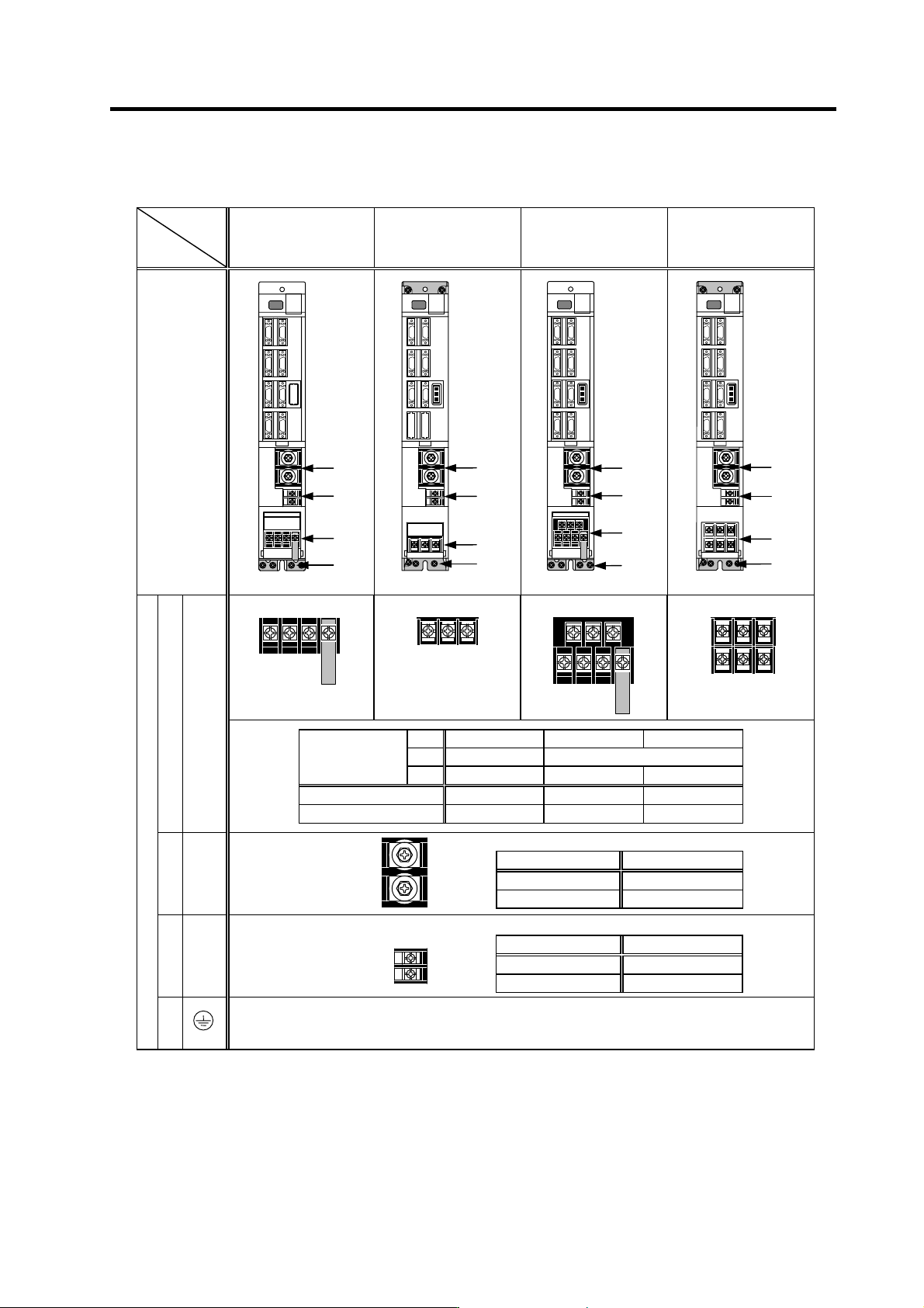
2. Wiring and Connection 2 - 7 (2) Control circuit connector Unit Terminal MDS-C1-V1 MDS-C1-V2 Connector position [1] CN1A [2] CN1B [3] CN9 [4] CN4 [5] CN2L [6] CN3L [7] CN2M [8] CN2M Connector s p ecifications [9] CN20 …
2. Wiring and Connection
2 - 6
Servo/spindle drive unit
Unit
Terminal
MDS-C1-V1-10 and
smaller
MDS-C1-SP-15 and
smaller
MDS-C1-V1-20 and
larger
MDS-C1-SP-22 and
larger
MDS-C1-V2-1010 and
smaller
MDS-C1-V2-2010 and
larger
Terminal
position
[1] TE1
V1- 01 to 35 45S,45 to 90 110 to 150
V2- 0101 to 9090S -
Compatible unit
SP- 04 to 37 55 to 185 220 to 300
Screw size M4 M5 M8
Tightening torque 2.0Nm 3.2Nm 13.2Nm
[2] TE2
Compatible unit All V1/V2/SP
Screw size M6
Tightening torque 5.0Nm
[3] TE3
Compatible unit All V1/V2/SP
Screw size M4
Tightening torque 2.0Nm
Terminal specification/Pin assignment
[4]
The PE screw size is the same as TE1.
[
2
]
[
3
]
[
1
]
[
4
]
[
2
]
[
3
]
[1]
[4]
[
2
]
[
3
]
[
1
]
[
4
]
[
2
]
[
3
]
[
1
]
[
4
]
MU MV MW
LU LV LW
MU MV MW
LU LV LW
U V W
U V W
L+
L-
L11
L21
2. Wiring and Connection
2 - 7
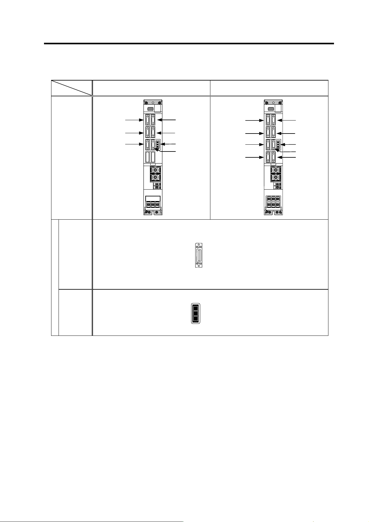
(2) Control circuit connector
Unit
Terminal
MDS-C1-V1 MDS-C1-V2
Connector
position
[1] CN1A
[2] CN1B
[3] CN9
[4] CN4
[5] CN2L
[6] CN3L
[7] CN2M
[8] CN2M
Connector s
p
ecifications
[9] CN20
(Note) The [5] and [6] connector names diff er for the MDS-C1-V1 unit. (CN2L, CN3L → CN2, CN3)
[
1
]
[
3
]
[
5
]
[
2
]
[
4
]
[
9
]
[
6
]
[
1
]
[
3
]
[
5
]
[
2
]
[
4
]
[
9
]
[
6
]
[
8
]
[
7
]
Pin No.
No.1
No.10
No.11
No.20
No.1
No.2
No.3
Pin No.
2. Wiring and Connection
2 - 8
2-3 NC and drive unit connection
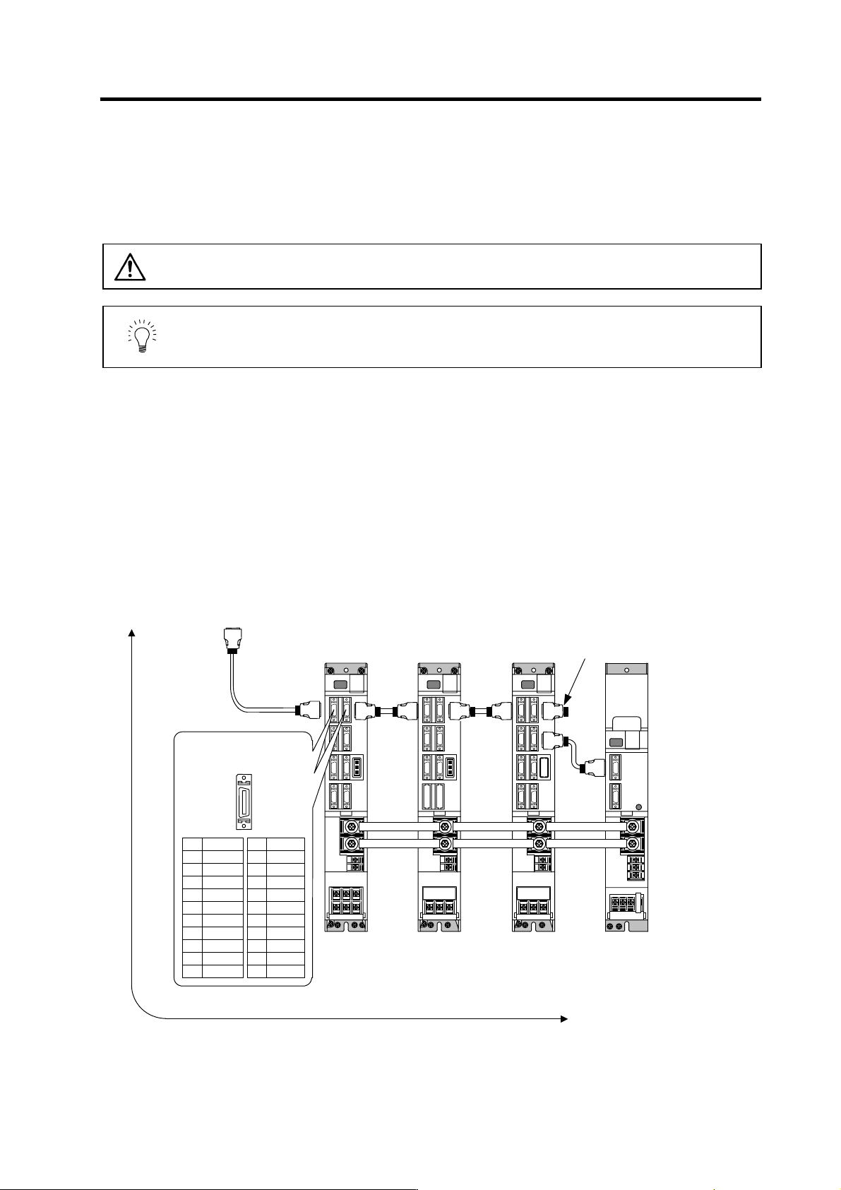
The NC bus cables are connected from the NC to each drive unit so that they run in a straight line from
the NC to the terminal connector (battery unit). And up to 7 axes can be connected per system.
Note that the number of connected axes is limited by the NC.
CAUTION
Wire the SH21 cable between the NC and drive unit so that the distance
between the NC and terminal connector (battery unit) is within 30m.
POINT
Axis Nos. are determined by the rotary switch for setting the axis No. (Refer to
section "3-1-1 Setting the rotary switch".) The axis No. has no relation to the
order for connecting to the NC.
(1) When using one power supply unit
Connect the largest-capacity spindle drive unit to the final axis of the NC communication bus in
order to control the power supply unit. The spindle drive unit must be installed adjacent to the power
supply unit. In the system with servo only, a servo drive unit for controlling unbalance axis must be
installed in the same manner in the same way.
< Connection >
CN1A : CN1B connector on NC or previous stage's drive unit
CN1B : CN1A connector on next stage's drive unit or terminal connector (battery unit)
CN4 : Connector for communication between power supply unit (master side) and drive unit
Connect to the battery unit with a
terminal connector or SH21 cable.
Refer to the
instruction manual
of each NC for
details.
Max. len
g
th of 30m from the NC to terminal connector or batter
y
unit.
CN1A
SH21 cable
MDS-C1-SP
4th axis (final axis)
MDS-C1-V1
3rd axis
Connected
to the NC
MDS-C1-CV MDS-C1-V2
1st/2nd axis
CN1B CN1A
CN1B
CN1A
CN1B
CN4
CN4
Pin No.
CN1A/CN1B
No.1
No.10
No.11
No.20
Name
GND
RD*
AL
SD*
GND
GFO
EMG*
P5
(
+5V
)
11
12
13
14
15
16
17
18
19
20
Name
GND
RD
AL
SD
GND
GFO
EMG
BAT
P5
(
+5V
)
1
2
3
4
5
6
7
8
9
10
Connection when using one power supply unit