bnp-b2365(eng)b.pdf - 第63页
2. Wiring and Connection 2 - 24 (2) Connection for semi-closed synchronous control (w hen using MDS-C1-V2 drive unit) MDS-C1-V2 Master axis Slave axis Detector cable CNV12 CN2L CN2M Parameter settings No. Abbrev . Parame…
2. Wiring and Connection
2 - 23
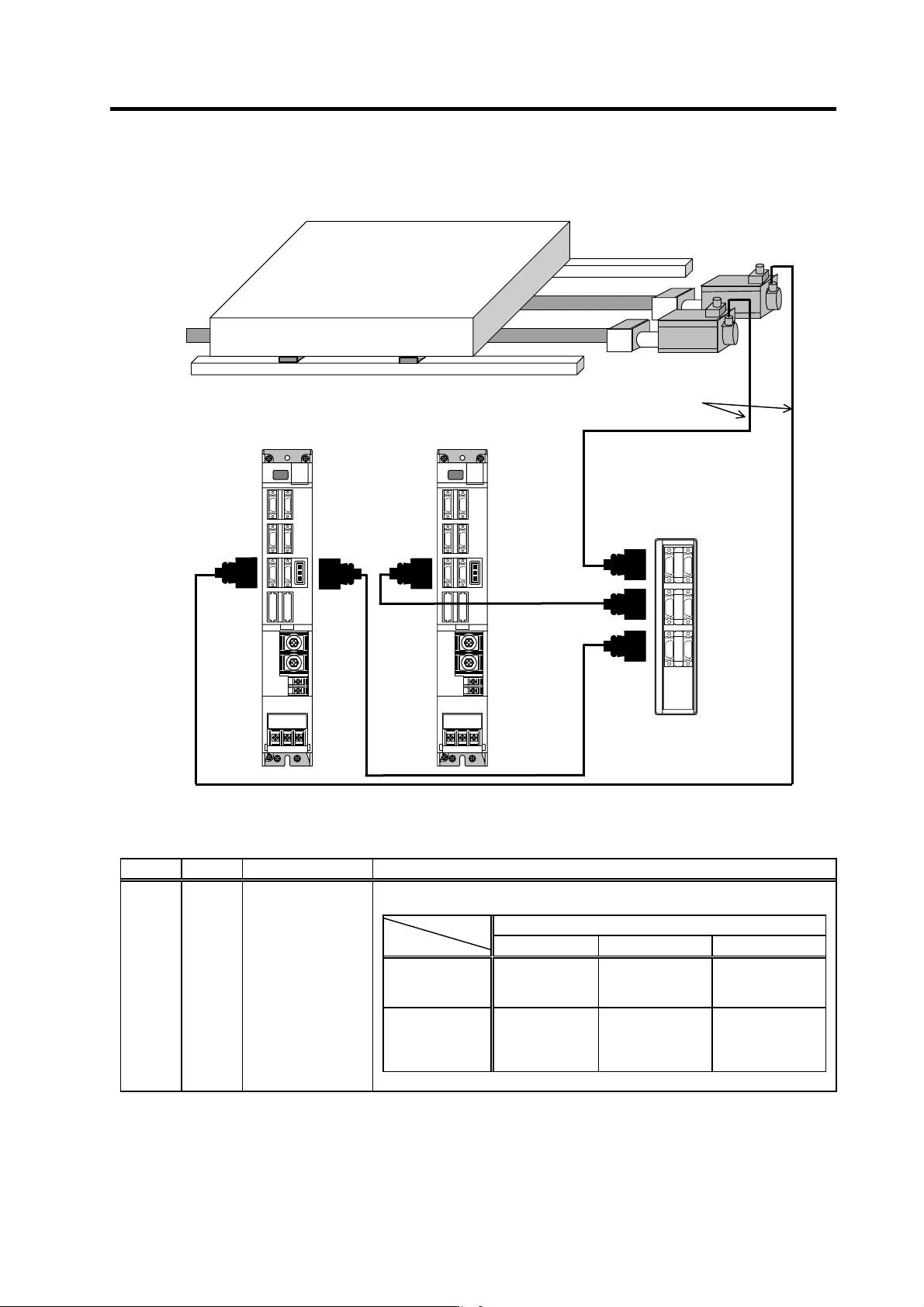
(1) Connection for semi-closed synchronous control (when using MDS-C1-V1 drive unit)
MDS-C1-V1
(Slave axis)
MDS-C1-V1
(Master axis)
Master axis
Slave axis
Detector cable
CNV12
MDS-B-SD
Signal distribution unit
CN2CN2
CN2A
CN2B
CN2
CN3
SH21
SH21
Parameter settings
No. Abbrev. Parameter name Description
Set the detector type. The value determined for each motor type is input to “xx” in the
following table.
Motor end detector type
OSE104/OSE105 OSA104 OSA105
Speed command
synchronous
control
Not compatible
Master axis =11xx
Slave axis =C1xx
Master axis =22xx
Slave axis =C2xx
Current
command
synchronous
control
Not compatible
Master axis =11xx
Slave axis =CCxx
Master axis =22xx
Slave axis =CCxx
SV025 MTYP Motor/detector type
(Note) A system in which two MDS-C1-V1 unit are used is not compatible with incremental system.
2. Wiring and Connection
2 - 24
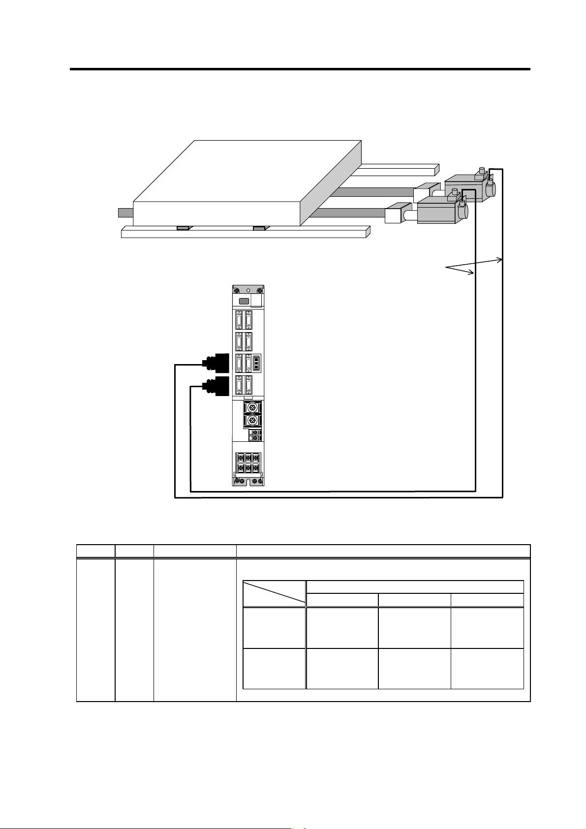
(2) Connection for semi-closed synchronous control (when using MDS-C1-V2 drive unit)
MDS-C1-V2
Master axis
Slave axis
Detector cable
CNV12
CN2L
CN2M
Parameter settings
No. Abbrev. Parameter name Description
Set the detector type. The value determined for each motor type is input to “xx” in the
following table.
Motor end detector type
OSE104 OSA104 OSE105/OSA105
Speed
command
synchronous
control
Master axis =00xx
Slave axis =C0xx
Master axis =11xx
Slave axis =C1xx
Master axis =22xx
Slave axis =C2xx
Current
command
synchronous
control
Master axis =00xx
Slave axis =CCxx
Master axis =11xx
Slave axis =CCxx
Master axis =22xx
Slave axis =CCxx
SV025 MTYP Motor/detector type
2. Wiring and Connection
2 - 25
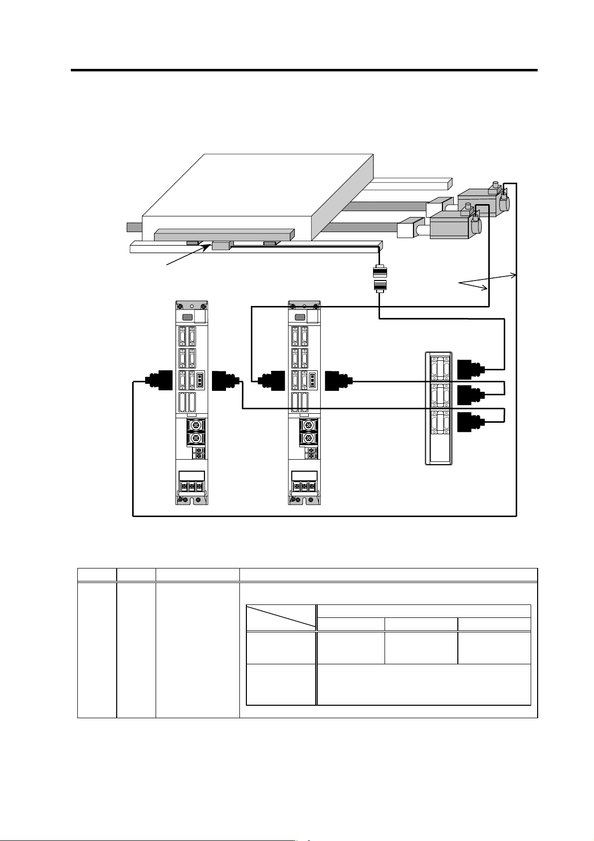
(3) Connection for full-closed synchronous control
(when using MDS-C1-V1 drive unit and serial output linear scale)
MDS-C1-V1
(Slave axis)
MDS-C1-V1
(Master axis)
Master axis
Slave axis
Detector cable
CNV12
MDS-B-SD
Signal distribution
unit
Linear scale
CN2
CN3 CN2 CN3
CN3
B
CN3
A
CN3
SH21
SH21
Parameter settings
No. Abbrev. Parameter name Description
Set the detector type. The value determined for each motor type is input to “xx” in the
following table.
Motor end detector type
OSE104/OSE105 OSA104 OSA105
Speed command
synchronous
control
Not compatible
Master axis =A1xx
Slave axis =D1xx
Master axis =A2xx
Slave axis =D2xx
Current
command
synchronous
control
Not compatible
SV025 MTYP Motor/detector type
(Note1) A system in which two MDS-C1-V1 unit are used is not compatible with incremental system.
(Note2) The full-closed system in which two MDS-C1-V1 units are used is not compatible with current command synchronous
control.