bnp-b2365(eng)b.pdf - 第91页
3. Setup 3 - 4 3-1-3 Servo standard specifications and high-gain specifications (1) Two-part system compliance With the MDS-C1-V1/V2 Series, control is possibl e with the standard servo (M DS-B-V1/V2) control mode and hi…
3. Setup
3 - 3
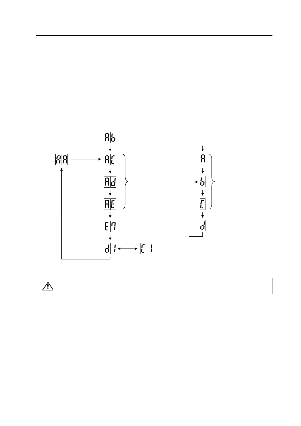
3-1-2 Transition of LED display after power is turned ON
When CNC, each drive unit and the power supply unit power have been turned ON, each unit will
automatically execute self-diagnosis and initial settings for operation, etc. The LEDs on the front of the
units will change as shown below according to the progression of these processes.
If an alarm occurs, the alarm No. will appear on the LEDs. Refer to "6-1 LED display when alarm or
warning occurs" for details on the alarm displays.
CAUTION
Always input emergency stop when starting the servo system.
Executing initial
communication with NC
Drive unit initialization complete
Waiting for NC power start up
Emergency stop state
The LED will alternate between
F# → E7 → not lit.
(# is the set axis No.)
Repeats lighting and going out.
(1st axis in the display example)
NC power ON
Waiting for NC
power start up
NC power OFF
NC power ON
LED display
Servo ON state Servo OFF sate
Drive units
Executing initial communication
with NC
A : Initializing
b : Ready OFF, in emergency stop
c : Ready ON/servo OFF
Emergency stop state
NC power
ON
LED display
Servo ON state
Power supply unit
3. Setup
3 - 4
3-1-3 Servo standard specifications and high-gain specifications
(1) Two-part system compliance
With the MDS-C1-V1/V2 Series, control is possible with the standard servo (MDS-B-V1/V2) control
mode and high-gain servo (MDS-B-V14/V24) control mode. When replacing an older model
(MDS-B Series) with this series, the servo parameter settings are automatically recognized and the
control mode is determined. Thus, the model can be changed from either a standard servo or
high-gain servo without changing the servo parameters.
When using the MDS-C1-V1/V2 unit and newly adjusting the machine, select the high-gain
specifications. The high-gain specifications are set as the default.
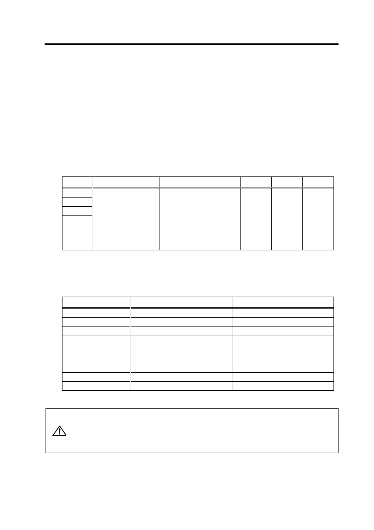
(2) Judging the control mode
Whether the servo drive unit starts up with the standard servo specifications or high-gain servo
specifications depends on the servo parameter SV009 to SV012 and SV033/bit8, 9 settings.
Parameter High-gain Standard Standard High-gain High-gain
SV009
SV010
SV011
SV012
SV009 = 4096 or more, and
SV010 = 4096 or more, and
SV011 = 768 or more, and
SV012 = 768 or more
Setting that does not satisfy even
one of the following conditions:
SV009 = 4096 or more
SV010 = 4096 or more
SV011 = 768 or more
SV012 = 768 or more
SV009=*
SV010=*
SV011=*
SV012=*
SV009=*
SV010=*
SV011=*
SV012=*
SV009=*
SV010=*
SV011=*
SV012=*
SV033/bit8 0 0 1 0 1
SV033/bit9 0 0 0 1 1
(Note) * indicates that there are no limits.
(3) Servo monitor unit type display
Whether the system is running with the high-gain servo or standard servo control mode can be
confirmed with the unit type displayed on the NC SERVO MONITOR screen.
Unit type For standard servo specifications For high-gain servo specifications
MDS-C1-V1- C1V1s C1V1-
MDS-C1-V2-{{ C1V2s{{ C1V2-{{
MDS-C1-V1-45S C1V1s4S C1V1-4S
MDS-C1-V1-70S C1V1s7S C1V1-7S
MDS-C1-V2-3510S C1V2s3510 C1V2-3510
MDS-C1-V2-3520S C1V2s3520 C1V2-3520
MDS-C1-V2-4545S C1V2s4S4S C1V2-4S4S
MDS-C1-V2-7070S C1V2s7S7S C1V2-7S7S
MDS-C1-V2-9090S C1V2s9S9S C1V2-9S9S
CAUTION
1. To change the control mode to the high-gain servo specifications after
replacing the unit from a standard servo (MDS-B-V1/V2), the parameters
must be changed and adjusted for high-gain servo use.
2. If alarm 7F occurs after setting the servo parameters, turn the servo drive
unit power ON again.
3. Setup
3 - 5
3-2 Setting the initial parameters for the servo drive unit
(High-gain specifications)
The servo parameters must be set before the servo system can be started up. The servo parameters
are input from the NC. The input method differs according to the NC being used, so refer to each NC
Instruction Manual.
3-2-1 Setting the standard parameters
When starting up the system, first set the standard parameters listed in "3-2-2 List of standard
parameters for each servomotor". For the parameters shown below, check the machine and servo
system specifications and determine the setting value.
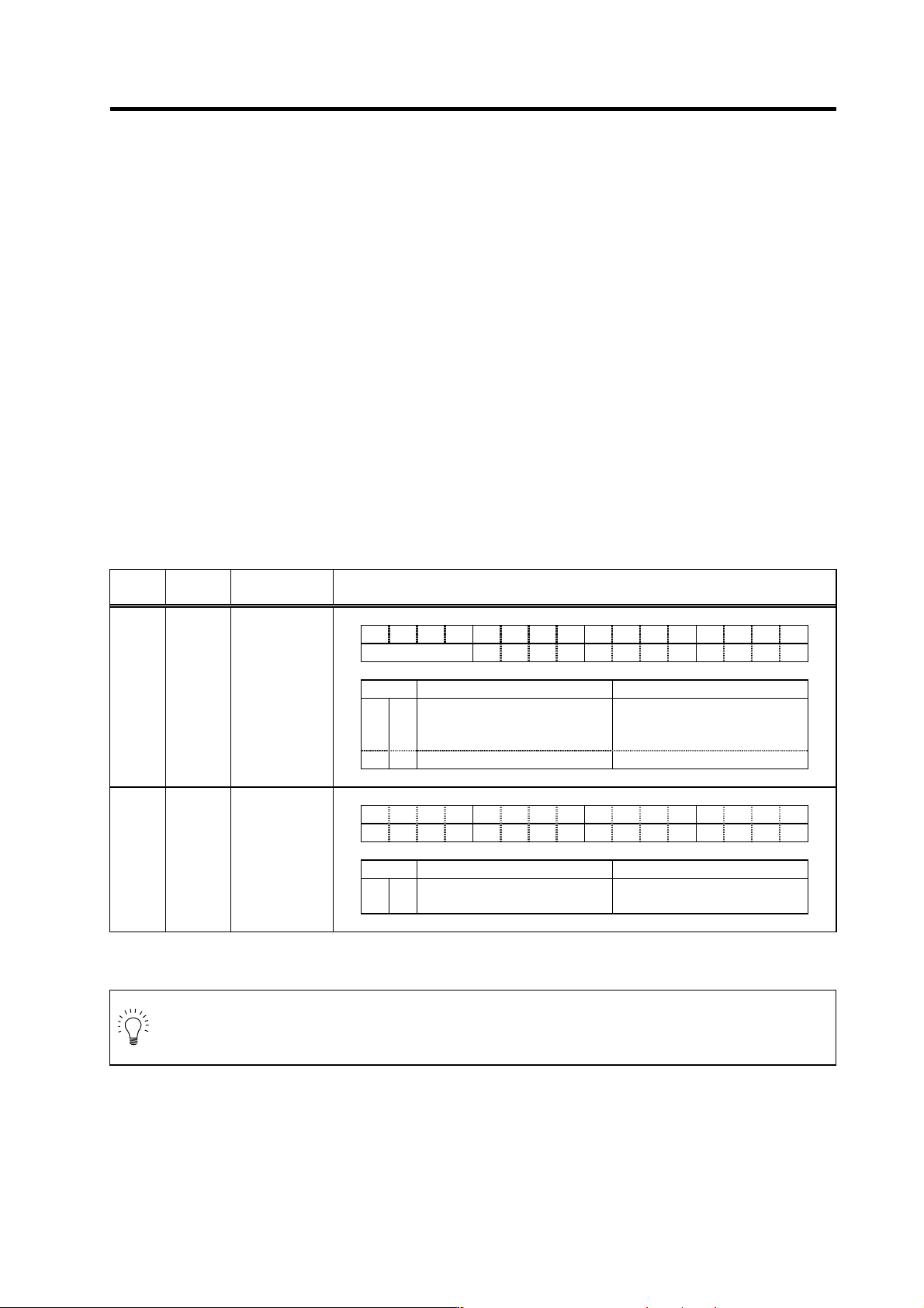
(1) Basic specification pa rameters
[1] When performing absolute position control, set SV017/bit7=1. This may be automatically set by
NC system parameter setting, depending on NC model. (Setting on the servo parameter screen
is not valid.)
[2] When performing absolute position control with speed and current synchronous control, set
SV081/bit4=1 for master and slave axes. Also set SV017/bit7=1.
[3] For HA053N, HA13N, HA23N, HA33N motors, if the connector direction of the motor end
detector with motor power connector is 90°, set SV017/bit5=1. If the angle is 180°, use a
standard setting (SV017/bit5=0).
Setting basic specification parameters
High-gain specifications
No. Abbrev.
Parameter
name
Explanation
F E D C B A 9 8 7 6 5 4 3 2 1 0
spm mpt mp abs vdir fdir vfb seqh dfbx fdir2
bit Meaning when "0" is set Meaning when "1" is set
5 vdir
Standard setting HA motor (4 pole motor)
Detector installation position 90
degrees (B, D)
7 abs Incremental control Absolute position control
SV017 SPEC*
Servo
specification
selection 1
F E D C B A 9 8 7 6 5 4 3 2 1 0
pabs rabs
bit Meaning when "0" is set Meaning when "1" is set
4 pabs Normal setting
Speed/current synchronous
control absolute position control
SV081 SPEC2*
Servo
specification
selction 2
Parameters with an asterisk * in the abbreviation, such as PC1*, are validated with the NC power turned ON again.
POINT
Setting of absolute position control (SV017/bit7) may be set automatically by NC
system parameter setting, depending on NC model. In this case, setting on the servo
parameter screen is not valid.